If you’re going to build a dyno that will be able to work in steady state (constant speed) or at least if you want to put some additional load during the runs, you need an absorber in your dyno. The dyno controller is able to control the torque output of the absorber to keep the engine at steady speed no matter what the engine power output is. Acceleration rate control or road simulation is also possible for dynamic runs. The most important choice you need to make is absorber selection. The terms you may hear for dyno absorber are: dyno brake, PAU (Power Absorption Unit), dyno retarder (from use for slowing down trucks).
You have several absorber types to choose from. The following table shows pros and cons of each absorber type:
| Air cooled Eddy brake | Water cooled Eddy brake | Magnetic powder brake | Electric motor | Water brake | Hydraulic pump | |
|---|---|---|---|---|---|---|
| Cost | Good | Poor | Fair | Poor | Very good | Fair |
| Size vs. power | Fair | Good | Fair | Poor | Very good | Good |
| Responsiveness | Very good | Very good | Very good | Excellent | Poor | Fair |
| Low speed ( < 500 RPM ) torque | Poor | Poor | Good | Excellent | Poor | Good |
| High speed compatibility | Fair | Good | Poor | Fair | Good | Poor |
Absorber sizing for roller dyno
Is bigger always better? Generally speaking yes, but on roller dyno at some point it becomes unused. The problem is the amount of available traction. With a powerful car, at some point, the wheels will just start spinning, even if your absorber still have more torque available. With small diameter rollers and big eddy brake, you will also hit the top rotational speed limit.
I’ll explain this with an example of BMW M5 F10 on a single roller dyno. The car has a 1990kg curb weight. Assuming the perfect 50:50 weight distribution that the BMW is so proud of, the weight on the roller will be 995kg. With perfect friction coefficient = 1.0, and g=9.81m/s² this gives us 9761N of tractive force.
| Roller diameter [cm] | Maximum absorber torque before slip [Nm] | Air cooled eddy brake with 50% headroom for heating [Nm] |
|---|---|---|
| 15 | 732 | 1098 |
| 30 | 1464 | 2196 |
| 45 | 2196 | 3294 |
| 60 | 2928 | 4392 |
| Road speed [km/h] | Max power on wheels before slip [PS] | Brake speed roller d=15cm [RPM] | Brake speed roller d=30cm [RPM] | Brake speed roller d=45cm [RPM] | Brake speed roller d=60cm [RPM] |
|---|---|---|---|---|---|
| 50 | 184 | 1768 | 884 | 589 | 442 |
| 100 | 369 | 3537 | 1768 | 1179 | 884 |
| 150 | 553 | 5305 | 2653 | 1768 | 1326 |
| 200 | 737 | 7074 | 3537 | 2358 | 1768 |
| 250 | 922 | 8842 | 4421 | 2947 | 2210 |
Keep in mind that these tables are based on a single conditions example that I mentioned to give you some general feeling of eddy brake sizing and power handling capacity of the dyno in steady state. Don’t forget some important points that significantly affect our starting assumptions:
- On motorcycle dyno, the vehicle puts less weight so the roller. Maximum torque before slip will be lower.
- On double roller dyno with unlinked rollers, only part of the force goes to roller with absorber. Maximum torque before slip will be lower.
- On truck dyno, heavy truck will put more weight on the rollers. Maximum torque before slip will be higher.
- You can design the dyno to be able to pull down the vehicle to the rollers with tie down straps. This will make the torque before slip higher.
Absorber sizing for hub dyno
One of the advantages of hub dyno is that the power you can measure is not limited by available traction. This feature is required on really powerful vehicles (over 1000PS) or if your vehicle has low top speed (short gearbox) and still some significant power. Here is some calculation of steady state hub torque for 2WD hub dyno assuming the vehicle had 225/40/R17 wheels (61cm diameter).
| Road speed [km/h] | 50 | 100 | 150 | 200 | 250 | 300 |
|---|---|---|---|---|---|---|
| Hub speed [RPM] | 433 | 867 | 1300 | 1734 | 2167 | 2601 |
| Hub torque [Nm] @ 500PS | 4051 | 2025 | 1350 | 1013 | 810 | 675 |
| Hub torque [Nm] @ 750PS | 6076 | 3038 | 2025 | 1519 | 1215 | 1013 |
| Hub torque [Nm] @ 1000PS | 8101 | 4051 | 2700 | 2025 | 1620 | 1350 |
| Hub torque [Nm] @ 1500PS | 12152 | 6076 | 4051 | 3038 | 2430 | 2025 |
| Hub torque [Nm] @ 2000PS | 16202 | 8101 | 5401 | 4051 | 3240 | 2700 |
| Hub torque [Nm] @ 2500PS | 20253 | 10126 | 6751 | 5063 | 4051 | 3375 |
Let’s assume that your vehicle is the one that can go up to 250km/h, and let’s consider air cooled eddy brake heat soaking.
| Power [PS] @ 250km/h | Raw hub torque requirement [Nm] | Short runs (+20%) | Steady state (+100%) | Endurance test (+200%) |
|---|---|---|---|---|
| 500 | 810 | 972 | 1620 | 2430 |
| 750 | 1215 | 1458 | 2430 | 3646 |
| 1000 | 1620 | 1944 | 3240 | 4861 |
| 1500 | 2430 | 2916 | 4861 | 7291 |
| 2000 | 3240 | 3889 | 6481 | 9721 |
| 2500 | 4051 | 4861 | 8101 | 12152 |
You can see why most of the serious builds of hub dynos use the biggest available eddy brakes on the market. The most popular choice is KLAM CFK-550 with peak torque 4660Nm. Dyno based on it will be able to measure runs of drag cars up to 2500PS and easily make endurance tests of vehicles up to 800PS. That doesn’t mean that smaller eddy brakes are not a valid choice for a hub dyno. If you know you will only be doing runs and short steady state on vehicles around 500PS even the popular Frenelsa F16-160 will do the job. Just remember that on hub dyno you don’t have big roller inertia to back you up when you run out of brake torque and the engine will rev up very quick.
Remember that these tables are based on some typical assumptions about vehicle wheel diameter and top speed. If you’re building a hub dyno for tractor pulling vehicle tests, the hub speed will be much lower and the required torque much higher.
Air cooled eddy current brake
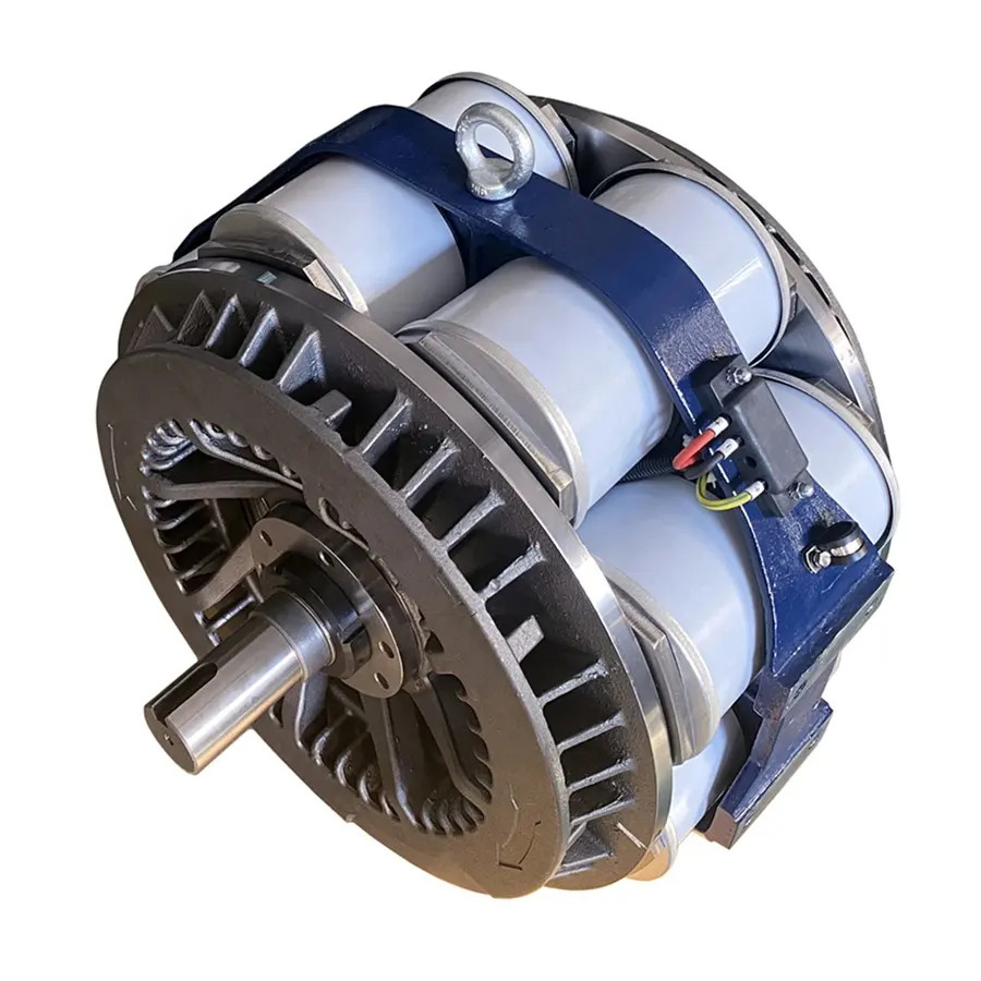
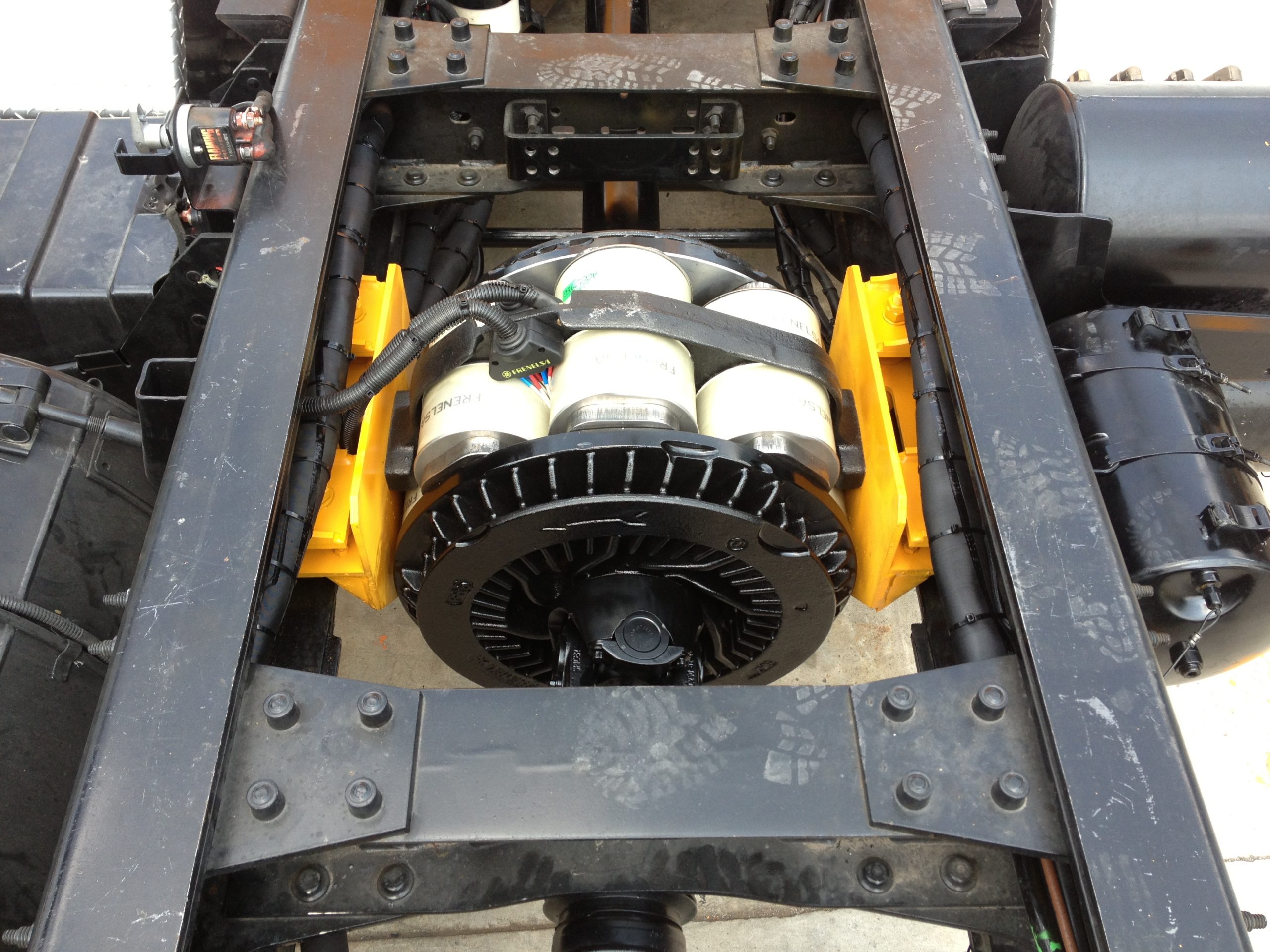
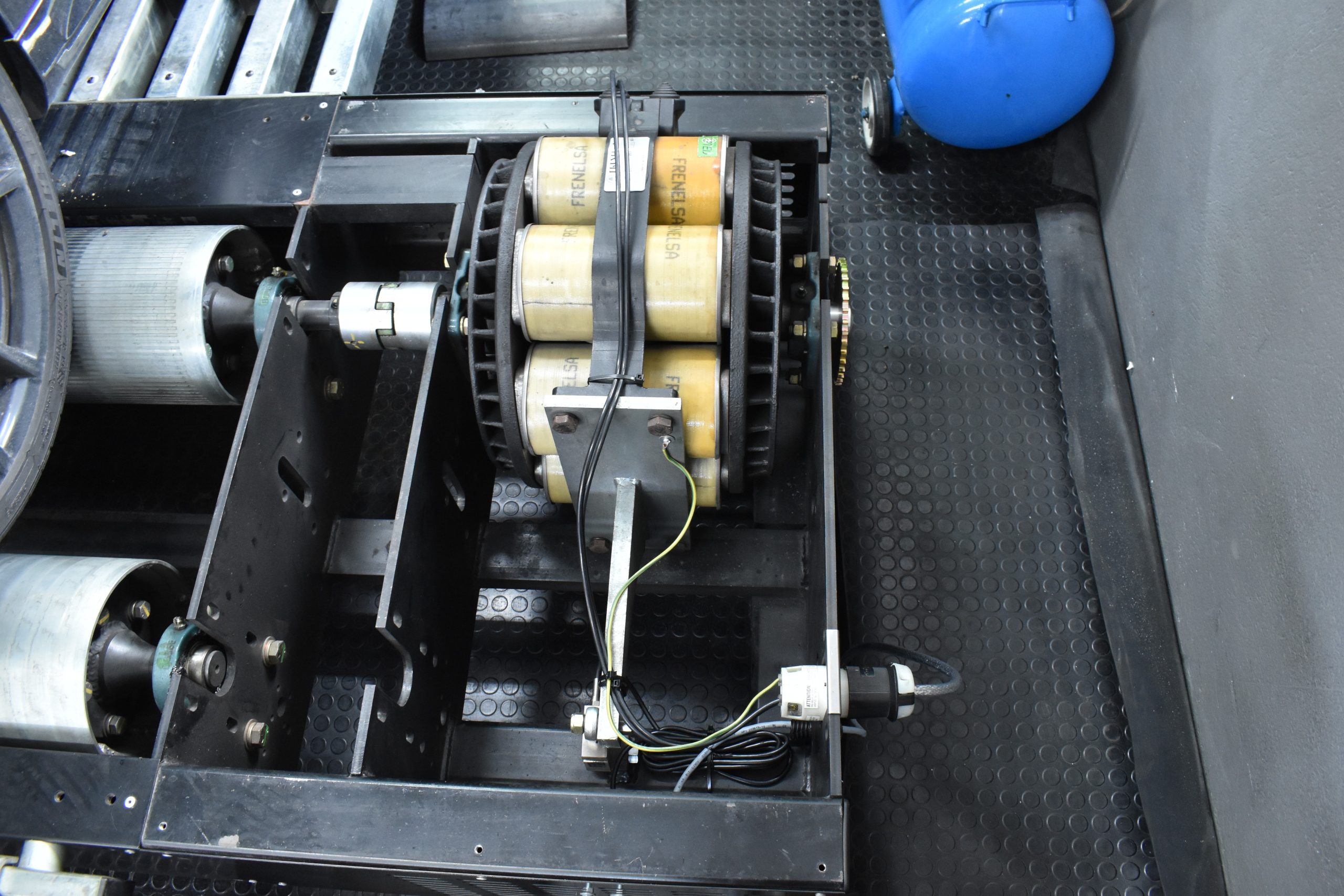
This type of absorber is often called just retarder. The term comes from its main use to slow down heavy trucks when coasting down the hill without wearing out friction brakes. It’s the most popular choice for dynos because of reasonable price, good performance and ease of installation and control. Even if new eddy brake price is too high for you, scrapyard pieces can be sourced from trucks at a reasonable price.
Eddy current brake is easy to install. Beside mechanical fitting, only electrical connection from power supply is required. It doesn’t need any external cooling system. Only remember to run it idling for some time after heavy runs to cool down with air flow.
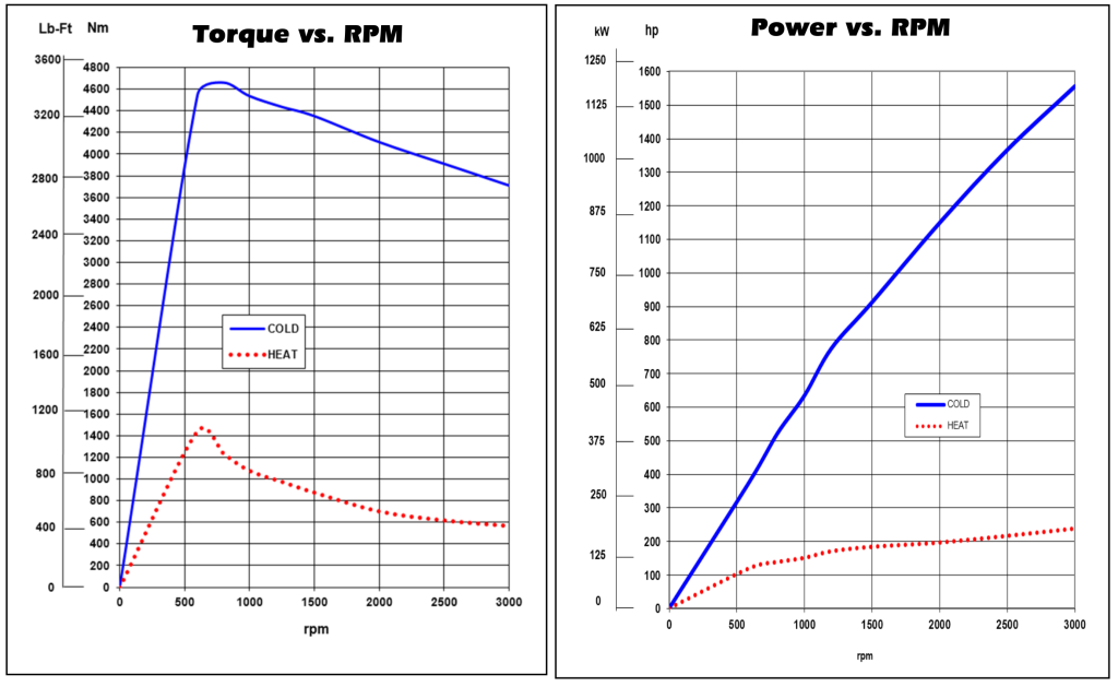
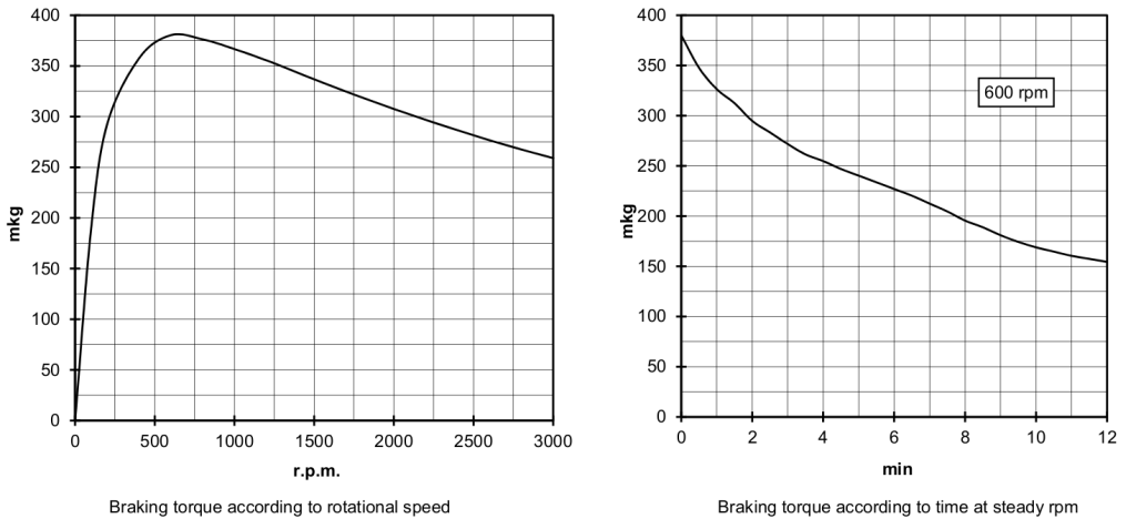
When selecting air cooled eddy brake there are few things to consider from the torque point of view.
- There is no torque available at 0 speed. The available torque rises linearly at low speed and curves on to the peak, that’s typically somewhere from 500RPM to 1000RPM. You can use the absorber below this peak, but the performance will poor. After this peak, the available torque drops with speed, but not as much as before it.
- When the absorber gets hot, it will produce less torque than the maximum nominal value. You need to consider this regarding your requirements for dyno use:
- Short power runs with breaks to cool down: add 20% to required torque
- Steady state tuning with some breaks: get 2x required torque
- Endurance testing: get 3x – 4x required torque
- Consider using gearbox to get the optimal eddy brake speed:
- Tractor PTO runs at 540RPM in low gear. If the tractor doesn’t have the high 1000RPM PTO speed, you may need to get a big absorber (even two), or multiply the speed by 2 with gearbox.
- On roller dyno you can manipulate the speed by choosing roller diameter. High diameter rollers will require bigger absorbers.
- On hub dyno you will typically work in optimal range over 100km/h road speed. On lower speeds and high power, the performance may be worse.
- On engine dyno with gasoline engine, you will run out of specified top speed for the absorber and typically need to reduce the speed by 2 with gearbox.
Eddy brake from scrapyard
There are few things to consider when sourcing the eddy brake from a scrapyard. Beside obvious mechanical condition, coil winding condition is important. Possible voltage options are also worth considering.
Coils condition
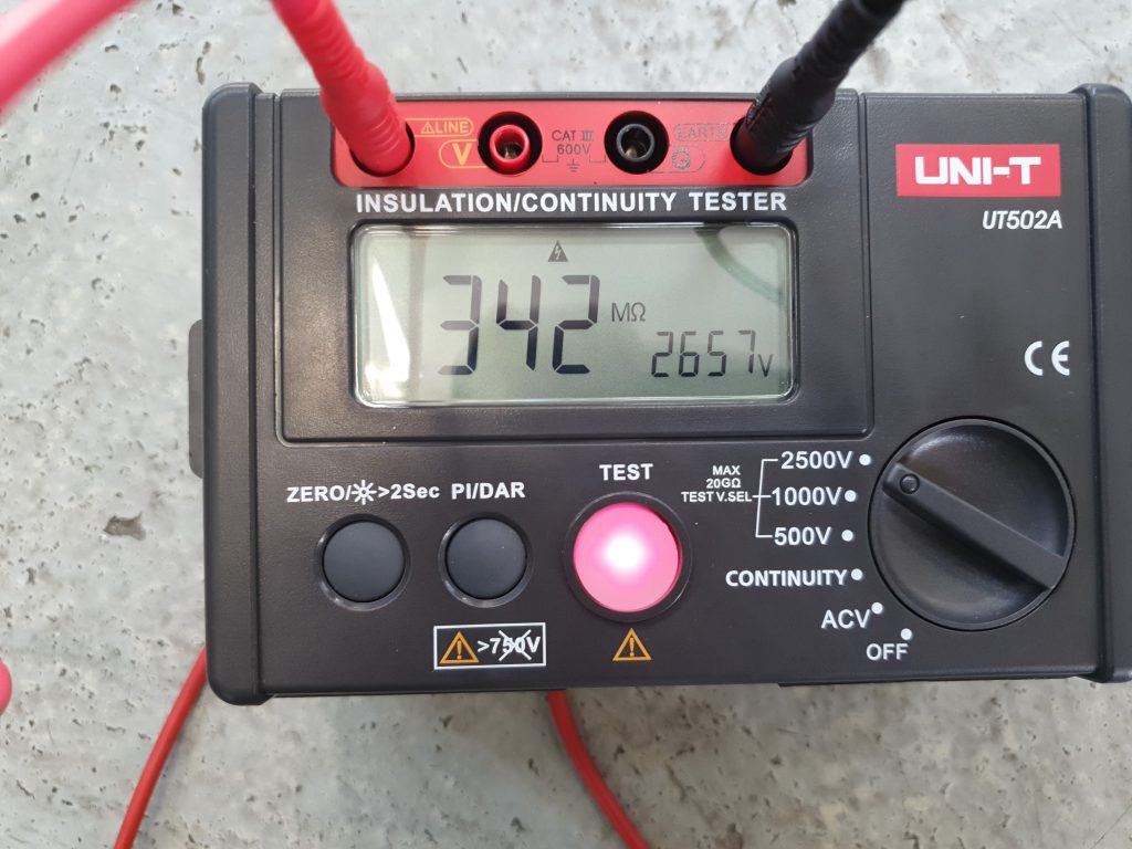
Coils insulation degrades when stored in humid, dirty conditions for long time. Don’t even look at the retarders from trucks dumped in the bushes or laying in the mud. When hunting for a good piece, borrow or buy an insulation tester to check if the insulation resistance is acceptable. Multimeter won’t help you with this. Before insulation test, the ground connection of the circuit must be disconnected from the frame. The test is made between windings and the frame. Test voltage must be at least 1500V and the result must be at least 1MOhm. The higher, the better. If the insulation resistance is low, cleaning and drying the retarder might help, but if it doesn’t then you will need to rewind the coils what adds cost and makes the choice of used retarder questionable. You should also check coil circuits for continuity. Sometimes you may find retarders with burned coils that will also require rewinding.
Coils voltage
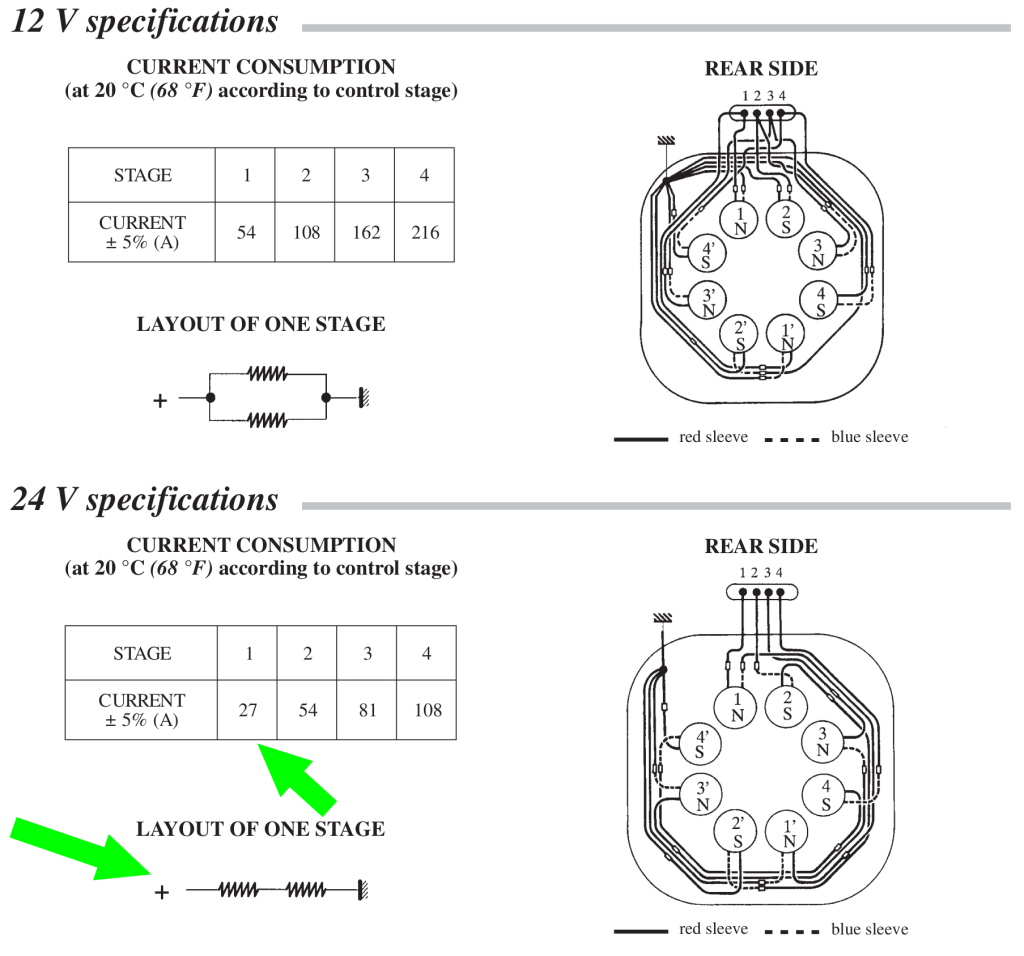
The power supply available in trucks and in your dyno cell is quite different. In trucks, you have low 12V or 24V voltage and few hundred amps of current available to be switched with relays. In your dyno cell you have mains 120VAC or 230VAC or even phase to phase 400VAC available with typically 16A circuit breakers (more in industrial location). Also, continuous digital current control gets more expensive with higher current. Because of these differences, the eddy brake wired for truck usually has coils connected in parallel (low voltage, high current) with four discrete braking levels selectable with hand control.
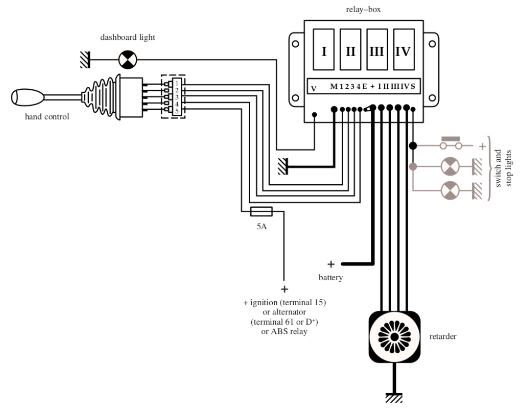
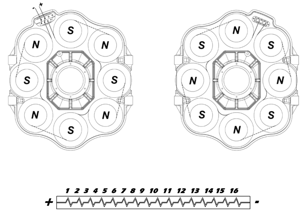
When using the brake in dyno, we want all coils in series (high voltage, low current), to better suit our power supply and control. Changing the connection doesn’t require rewinding the coils. You only need to identify coil connecting wires and connect all of them in series. It’s important to keep the interchanging magnetic polarity of coils. Messing it up will reduce generated torque significantly.
Another thing to consider is the current requirement of the absorber after connecting coils in series. If you have documentation for the absorber, look for single stage current with coils connected in series. You can also measure single coil resistance and figure out the voltage it gets in original connection. Then the current will be I=U/R. Typically, after connecting all coils in series, you will get a circuit that requires current from 15 to 35A. Higher current will require more powerful and expensive supply. The PEREK BD3 supplies are rated up to 22.5A, 30A and 45A.
Unknown specifications
Last of the problems with scrapyard eddy brake may be lack of nameplate or unavailable specification. You can solve problem of electrical specification by using multimeter and measuring coils resistance. This will help you to estimate required current. What about available torque? I have a quick solution for you. You can weight the absorber. Typically absorbers have around 10Nm of peak torque per 1kg of weight. So if you find a 200kg absorber you can expect it to have around 2000Nm of peak torque.
Water cooled eddy brake
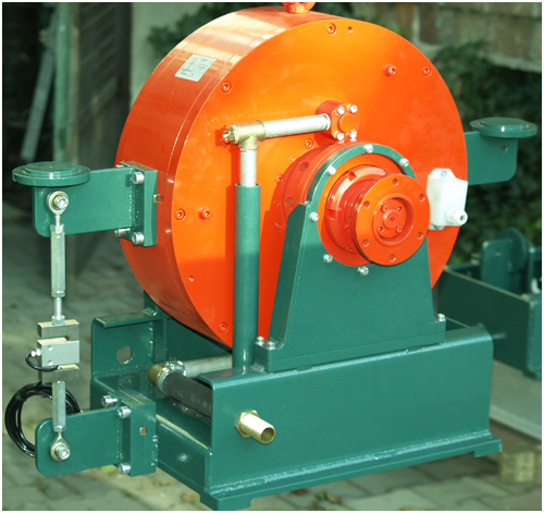
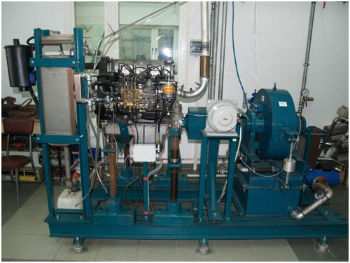
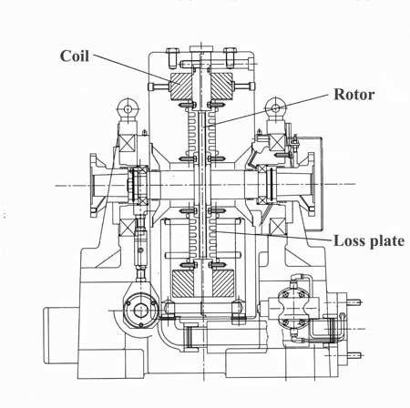
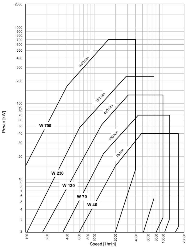
Most of the information about air cooled eddy brakes apply also to water cooled eddy current brakes. However, there are few differences that need to be pointed out. Water cooled eddy brake:
- Allow to easily extract the absorbed heat out of the dyno cell to the outside radiator, making it suitable for high-end professional laboratory dyno cells with climate control.
- It can sustain the nominal torque for long periods, so no oversizing is required as with air cooled brake.
- Due to smaller size and higher allowable speeds, it is suitable to be used without gearbox on engine dynos.
- And the last point to kill the mood: water cooled eddy brake is roughly 10 times more expensive than air cooled one.
Magnetic powder brake
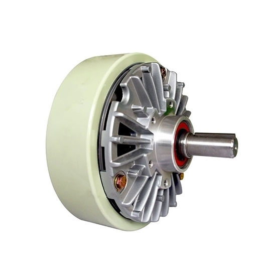
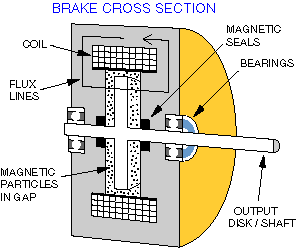
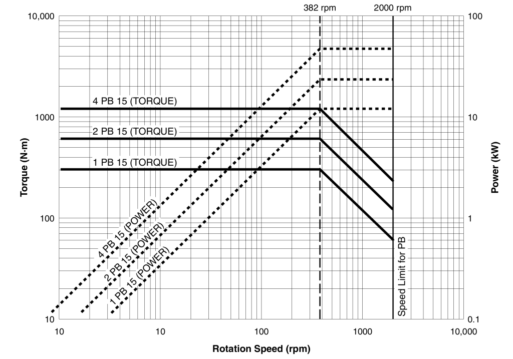
That’s the last of the family of brakes controlled with DC current. This brake, instead of using eddy current effect, uses a magnetic powder excited by current to create friction. The most significant difference from eddy brakes is that it can create torque from 0 speed, that’s why it is also called a magnetic clutch. The downside is that due to poor heat dissipation, it can’t be used at high speeds. Usually the dyno doesn’t require high torque at low speeds, so the classical eddy brake is the weapon of choice, however if this capability is required, then a tandem configuration of eddy brake and powder brake can be used to create dyno with a versatile torque characteristic.
Electric motor
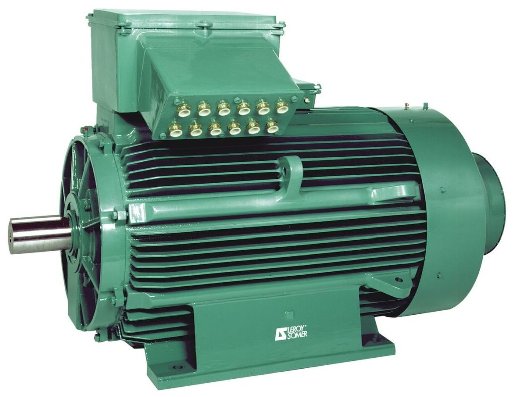
The electric motor is the high-end, high-cost solution to the dyno absorber with unmatched performance. Let’s break it down in pros – cons list.
Pros:
- Fast response
- High torque available from low speeds
- Motoring capability
- Can drive undriven vehicle wheels
- Can be used as a starter on engine dyno
- Can drive the engine to measure friction and pumping losses
- Can generate power to be sold back to mains grid
Cons:
- Expensive
- Big and heavy
- Motoring on chassis dyno requires high power from the mains grid
Water brake
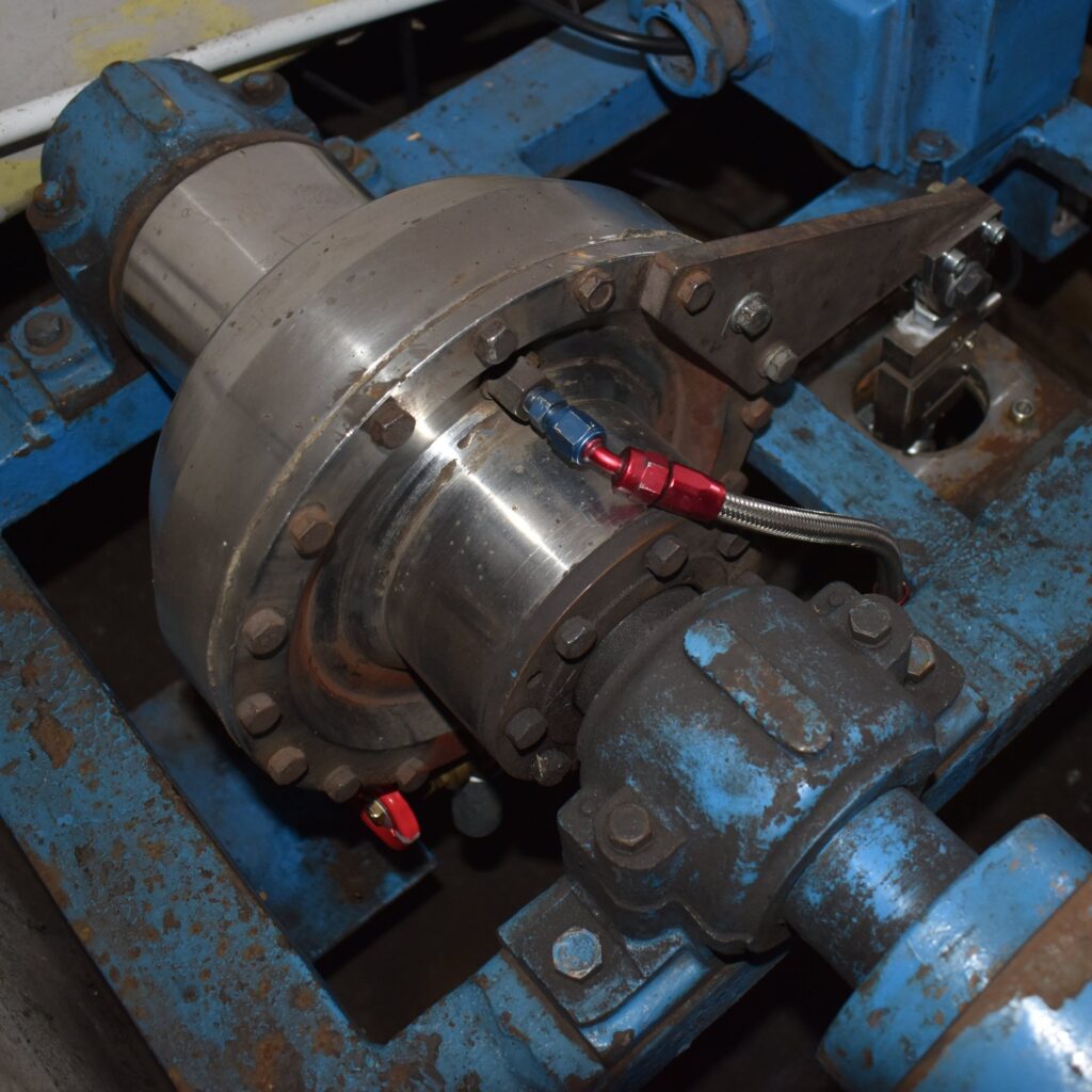
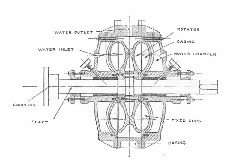
The water absorber is a popular choice for hobbyist dyno due to low cost, small size, high power capacity and high speed compatibility (direct connection to engine). The downside is a slow response and the need to create a plumbing system for water.
The braking torque of the water absorber is controlled by a valve on the inlet to the brake. It is done automatically by the dyno controller. The brake also should have a vent to allow the air to move in and out of the brake. The outlet valve to let the water out should also be automatically controlled for fast response.
The elephant in the room is the slow response of the brake. The torque in a water brake is not directly connected with the opening of the inlet valve, but rather with how much the brake is filled with water at the moment. The response of a water absorber is generally many times slower than any of the electric brakes mentioned earlier. An important thing to point out is that the response performance is greatly dependent on the instrumentation around the brake.
With high flow and pressure water supply, fast high flow inlet valve, efficient vent and automatically controlled, efficient outlet valve, the water brake can have a quite nice and usable response time.
With low capacity water supply, small inlet valve, manually controlled outlet valve, the brake response will be terribly slow. It will struggle to control the engine speed or acceleration when power output changes and it will disappoint you. It will be only suitable for endurance testing of the engine at steady power output or to add some not precisely defined load to the acceleration runs.
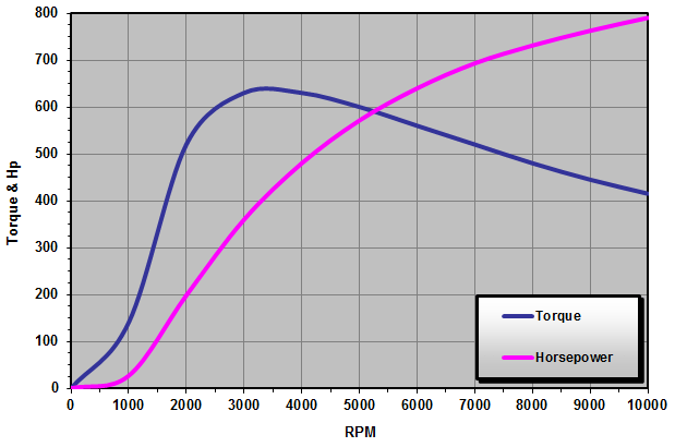
A good idea for a versatile dyno would be to connect in tandem an air cooled eddy current brake with water brake. The eddy brake will provide fast response, while the water brake will provide affordable, long term power absorbing capability.
Hydraulic pump
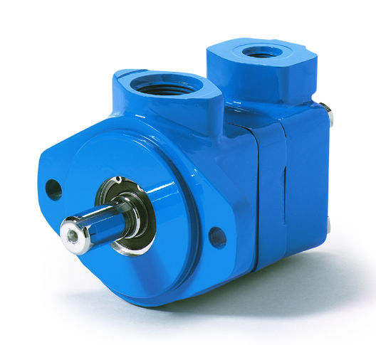
Hydraulic pump is another example of affordable absorber for hobbyists. The dyno equipped with this absorber works by restricting the flow of a hydraulic pump with a valve. Responsiveness of this solution is quite good, because it doesn’t lag while filling up like the water brake, and it responds quickly to the restriction of the flow. If you don’t buy a pump that has a build in safety relief valve, make sure to install an external one to save the pump and plumbing from bursting if the pressure gets too high.
Power that the dyno will be able to absorb can be calculated using the equation: Power = Flow * Pressure / Efficiency.
Pumps often specify the displacement per revolution, so Flow = Displacement * Speed.
