An engine knock detection system is a vital component in modern engine tuning that helps monitor and detect the occurrence of engine knock or detonation. Engine knock refers to the undesirable phenomenon where the air-fuel mixture in the combustion chamber ignites prematurely and creates a knocking or pinging sound. This can lead to engine damage and reduced performance if not addressed promptly. The knock detection system in DC series controllers utilizes an external sound card and standard knock sensor. All required components for knock detection can be purchased here: Knock sensor set. By providing yourself real-time knock monitoring, you can protect the engine from potentially harmful conditions.

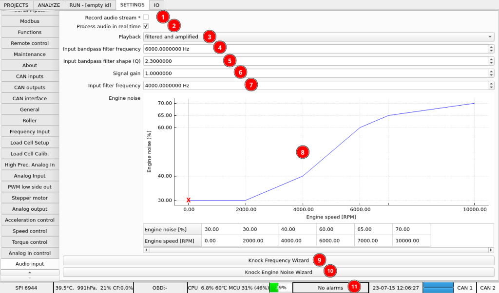
- Check this option to record audio stream with the run. This option is NOT required for basic system operation. It is required if you want to listen to the knock recording after you make the run. Keep in mind that recording a full audio stream will make your run files significantly larger.
- Process audio in real time option enables the audio processing system that calculates audio levels and knock values.
- Playback options for audio output. Real-time raw or processed audio can be played to the audio output (headphones) to let you monitor knocking sound yourself.
- The audio signal is first filtered with a band-pass filter to leave only the signal at knock resonant frequency and filter out all the other noise. Knock frequency can be calculated with Knock Frequency Wizard (9) or can be experimentally measured. Watch videos at the bottom for more details.
- Filter shape defines how wide is the band-pass filter. A wider filter will allow for a wider knock frequency to pass to further processing. A narrower filter will remove more unwanted noise.
- Signal gain after filter. Adjust to always have normal operation audio level below 60% to have some headroom to detect knocking.
- Input filter frequency is a cutoff frequency low-pass filter that works on the audio level calculated from the audio signal. Setting lower frequency will filter out noise or subtle knocking that has energy.
- Engine noise characteristic is used to define what audio level is acceptable for normal engine operation. All the signals that go above the engine noise characteristic will be interpreted as engine knock.
- Wizard to calculate band-pass filter frequency from cylinder diameter.
- Wizard to generate engine noise characteristic from a run that you are sure has no knock.
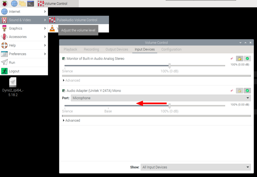
- While using the knock system, observe the alarm status. Even with the processed signal within 0-100% range, it is possible that the input raw signal is clipped. If you see “Audio input clipping” alarm, reduce microphone input gain in the Raspberry Pi system configuration

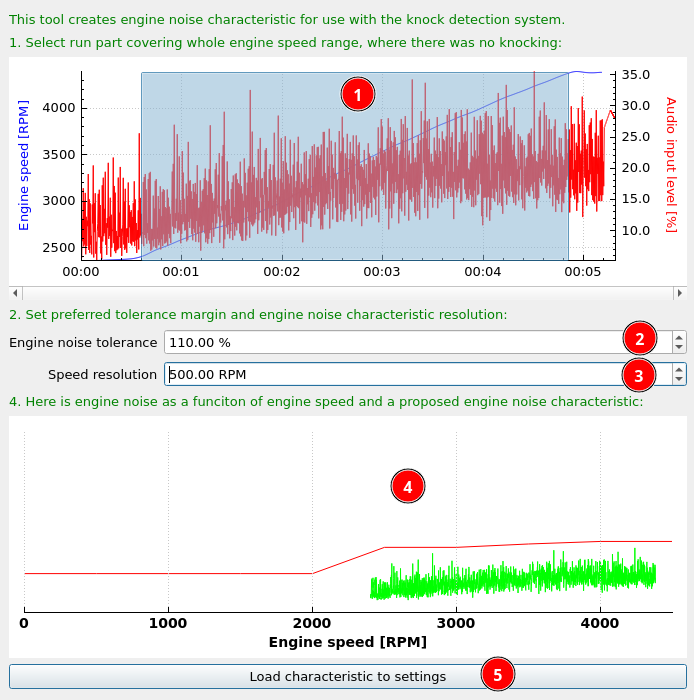
Knock engine noise characteristic can be quickly created with Knock Engine Noise Wizard. To make the characteristic, first make a run with knock sensor connected where you are sure that the engine is not knocking. Then click the wizard and load the run to create the characteristic.

- Select the run range that will be used to create the characteristic
- Engine noise tolerance allows you to give some additional margin above recorded noise that will still not be interpreted as knock.
- Speed resolution defines how many characteristic points should be created. Usually something around 500RPM is optimal. Too low value will wrap the characteristic tightly around audio level spikes and will cause false knock detection if the spike occurs at a different engine speed.
- Characteristic preview
- After you’re happy with the characteristic, load it to settings.
The audio knock system provides the following channels:
- audio_level – audio signal level after all processing
- audio_levelPeak – this channel is used as an audio level peak detector. Adjust this channel filter time to fit your preference for peak decay. By default, it is set to 1s, and it should be set above 0s.
- audio_knockLevel = audio_level – engine noise
- audio_knockCount – this channel is a counter that increments every time the audio_knockLevel goes above 0.
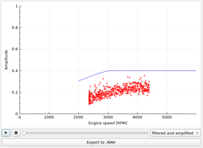
If you check the “Record audio stream” option and make a run, in the ANALYZE tab in run list under right-click the “Analyze knock recording” option will run the Knock Player tool. The Knock Player can play back the recorder stream raw or processed and export it to WAV file. While playing back the stream, data points are plotted together with saved engine noise characteristic. By using this tool, you can check yourself the recorded signal to determine if the knock detection system operation is correct.

