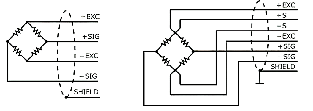
The load cell is built from 4 strain gauges arranged in a Wheatstone bridge. The resistances of gauges are in the range of hundreds of ohms. This type of load cell can be directly connected to DC2 series dyno controllers.
The shield wire in both cases goes to SHLD terminal in the controller.
If the wiring of the load cell is not known, the following procedure can be followed to find the correct connection with use of a simple multimeter:
6 wire load cell
- Measure resistances between load cell wires. Look for a wire pair that has resistance near 0 Ohm (short circuit). Connect both wires to EXC+ in the controller.
- Look for another pair of wires with 0 Ohm resistance. Connect them to EXC- in the controller.
- The remaining two wires go to SIG+ and to SIG-. Order is not important.
4 wire load cell
- Measure resistances between load cell wires. There are 6 measurements to make. 2 measurements will have higher resistance than the others.
- If from these 2 wire pairs there is one with a higher resistance, connect it to EXC+ and EXC-. Order is not important
- If both are the same, then it doesn’t matter which pair goes to EXC+ and EXC-.
- The remaining two wires go to SIG+ and to SIG-. Order is not important.
Basic health check of a load cell
Resistance check
Measure resistance between EXC+ and EXC−
Typical values are around few hundred ohms.
Do the same measurement between SIG+ and SIG-
If you read:
- Open circuit – broken wire or damaged gauge
- Very low (<10 Ohm) – short circuit
Symmetry check
Measure resistance:
- EXC+ : SIG+
- EXC+ : SIG−
- EXC− : SIG+
- EXC− : SIG−
All 4 measurements should be the same. If they are not, then the wiring is damaged or the cell was overloaded.
Insulation check
Check resistance between any EXC/SIG wire and load cell body (metal). There should be no connection (high resistance). If there is a connection then the insulation of the load cell wiring is damaged.
Functional test
Supply voltage between EXC+ and EXC-. The suitable voltage range is 5V-12V.
Measure voltage between SIG+ and SIG-.
Without load the voltage should be 0mV
With load:
SIG voltage = EXC voltage * load cell sensitivity * load / rated load
The voltage under load will be around few mV and change smoothly with load. Lack of voltage or jumpy reading indicates damaged gauge.