BD1 is discontinued. The closest replacement is BD2, but there are no longer BD series power supplies with built-in load cell amplifier, as it is not needed with DC2 series dyno controllers.
Device description
Brake power supply is intended for use with mains supplied eddy current brake. It is used for the following tasks:
- Rectification of mains AC voltage to DC voltage for brake supply
- Brake force modulation according to logic level, Pulse Width Modulation input signal
- Amplification of load cell signal to 0-5V level
Safety precautions
- The device should be fixed on a hard, flat surface in a well-ventilated area.
- The device must not be exposed to vibration.
- The device air flow must not be obstructed.
- No foreign objects should be inserted into the device.
- Life-threatening, high voltages are present in the device. Make sure that it is disconnected from mains power supply before doing maintenance work.
- The device is intended for installation by qualified personnel.
- The device should be protected from access by unauthorized personnel.
- The device should be protected from moisture. It mustn’t be used when wet.
- The device should be protected from ingress of conductive contaminants. It shouldn’t be operated where metal grinding or cutting dust is present in the air.
- The device mustn’t be powered without the enclosure assembled.
- Device installation doesn’t require enclosure disassembly.
- If the device is not working correctly, makes disturbing noises, emits burning smell, it should be immediately powered down. Please contact the manufacturer for repair.
- Device power supply must be protected with an over current circuit breaker. The breaker value should be selected to a minimum that is sufficient to supply the brake. If current requirement is unknown, a good starting value would be 25Amp for single phase supply and 10Amp for multiphase supply.
- All dyno metal elements must be connected to safety ground. Any short circuit of live wire to dyno chassis must result in circuit breaker opening. Use of RCD breaker is advised for additional safety.
Specification
| Supply | 85-240VAC, 50-60Hz, 1-3 phase |
| Brake peak current | 32A for 1s |
| Brake continuous current | 16A@50°C ambient temperature 17.5A@40°C ambient temperature 20A@25°C ambient temperature |
| Brake discharge method | Freewheeling diode |
| Maximum PWM modulation frequency | 2500Hz |
| Maximum PWM input voltage (CTRL, CTRL INV) | 24V |
| ON threshold for CTRL input | >3.5V |
| ON threshold for CTRL INV input | <1.5V |
| CTRL / CTRL INV leakage current | <5mA |
| +5V output current capacity | 0.3A |
| LCOUT load cell output impedance | 100Ohm |
| LCOUT load cell output voltage swing | 1.2V – 3.8V |
| LCOUT zero load voltage | 2.5V |
| Load cell signal amplification | older devices: g=495 (no info on label) new devices: g=106 (indicated on the label) |
| Environment temperature range | −20°C ÷ 50°C |
| Internal thermal protection threshold | 100°C |
| Operating humidity | 0% ÷ 95% without condensation |
| Elevation | Up to 1000 m.a.s.l. |
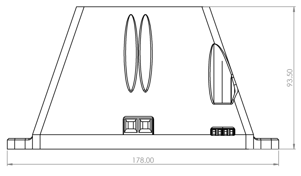
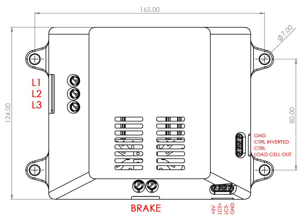
| Dimensions | 18cm x 13cm x 9.5cm |
| Mass | 607g |
Device connection
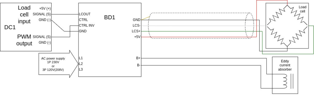
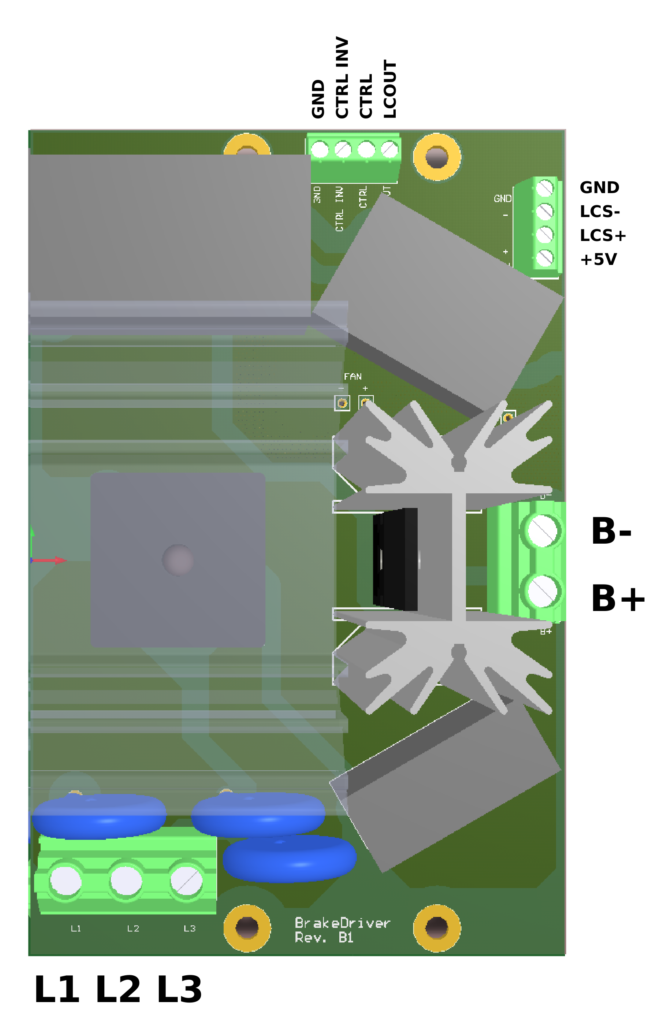
| Terminal | Description |
|---|---|
| GND | Return ground for control signal and LCOUT |
| CTRL | PWM control input activated with high voltage level ( U > 3.5V ) |
| CRTL INV | PWM control input activated with low voltage level ( U < 1.5V ) |
| LCOUT | Amplified load cell signal ( 0V – 5V ) |
| GND | Load cell supply ground return / shield |
| LCS+ | Load cell signal + |
| LCS- | Load cell signal – |
| +5V | Load cell supply voltage |
| B-, B+ | Eddy current brake output |
| L1, L2, L3 | Mains supply inputs |
Mains supply terminals L1,L2,L3 and brake terminals B-, B+ are separated from load cell and control signals. As a result, GND terminals can be connected to external control device GND not related to the L1, L2, L3 supply ground.
| BD1 terminal | 1 phase 120V or 1 phase 230V | 3 phase 120V(208V) | 3 phase 230V(400V) |
|---|---|---|---|
| L1 | Neutral | Phase 1 | Not allowed |
| L2 | Phase | Phase 2 | |
| L3 | Phase 3 |
WARNING! Voltages in the device are life-threatening. All connections should be made with the device disconnected from main supply. Connecting the supply is allowed only when the device is safely installed, and its enclosure is assembled.
It’s advised to bundle wires in 4 separated groups: control, load cell, brake and supply. Routing high voltage brake or supply wires parallel to load cell or control wires can lead to improper system operation.
Typical required cross-section of power cables is 2.5mm² up to 17A and 4mm² up to 23A.
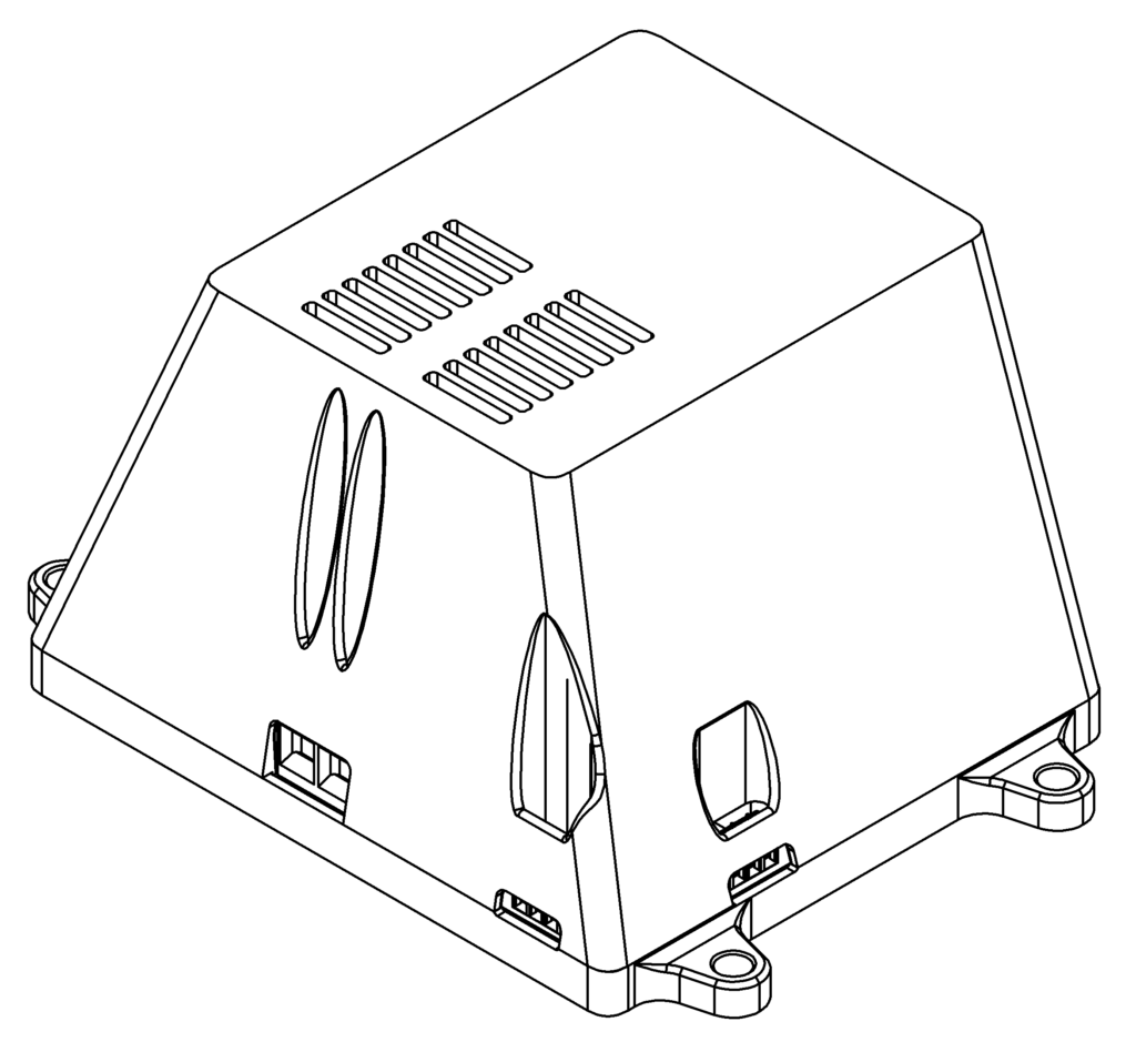
Technical drawings
Warranty
The producer guarantees that the device is manufactured according to accepted craftsmanship practices, and it meets the applicable standards. Correct device operation is guaranteed for 24-month period starting from date of purchase.
The guarantee does not cover damages caused by improper installation, usage or noncompliance with instruction manual.
The device is intended for installation by qualified personnel. Device final performance and suitability for a particular application is dependent on the user, and thus it is not guaranteed by the manufacturer.
These specifications are subject to change without notice.