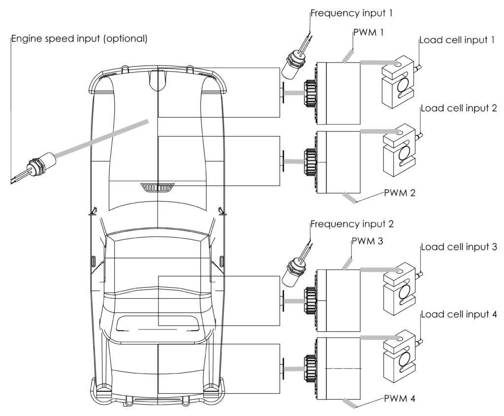
Sensors wiring
First / second roller set speed sensor – Frequency input 1 / 2
Brake torque sensor – according to the drawing – Load cell input 1 – 4
When there is no constant speed ratio between dyno shaft and engine shaft and engine torque calculation is required, an optional engine speed sensor can be connected to the Engine speed input.
Actuators wiring
A signal, used to control the brake on the dyno shaft, can be routed to Low side PWM output or Analog output or to BD3 via CAN bus. Low side PWM is a Low Side / Open Collector output with pull-up resistor to +12V.
The absorbers can be controlled in pairs or independently:
Absorber 1 control at Frequency input 1 – Low side PWM 1
Absorber 2 control at Frequency input 1 – Low side PWM 2
Absorber 3 control at Frequency input 2 – Low side PWM 3
Absorber 4 control at Frequency input 2 – Low side PWM 4
The specific assignment of Frequency input and output to the absorber is made later in the software.
BD1 brake power supply connection
| DC1 Dyno Controller terminal | BD1 Brake power supply terminal |
| Load cell input n / – | GND |
| Low side PWM n / S | CTRL INV |
| Not connected | CTRL |
| Load cell input n / S | LCOUT |
Software configuration
SETTINGS:
- General
- Dyno type – chassis
- Loss from load factor – percent of power lost on tire to roller transfer. Typically: 5% – 10%.
- Absorber dyno – checked if absorber is used
- Roller
- 1, 2
- Roller diameter – diameters of dyno roller
- Speed source – frequency input
- Connected inertia – total inertia of roller set rotating at speed measured by the input
- 1, 2
- Frequency Input
- 1, 2
- Sensor type – shaft speed sensor
- Frequency low pass filter – usually 10Hz to 20Hz – filters speed fluctuations
- Frequency change low pass filter – usually 1Hz to 5Hz – filter for frequency time derivative – filters power resulting from acceleration of rotational inertia
- Signals per rotation – signal count per dyno shaft rotation
- 3, 4
- Sensor type – if unused, must be set to “general purpose sensor”
- Engine Speed – Parameters for optional engine speed sensor
- 1, 2
- Load Cell
- 1 / Measures torque on – roller 1
- 2 / Measures torque on – roller 1
- 3 / Measures torque on – roller 2
- 4 / Measures torque on – roller 2
- 1-4
- Gain, Offset – load cell calibration coefficients should be set with Wizard tool.
- Low pass filter – usually 1Hz to 5Hz. It’s best to set the same value as for associated Frequency Input / Frequency change low pass filter
- [unused load cell] / Measures torque on – none
- PWM low side output setup ‘n’
- Source – “torque controller ‘n’ output” – if PWM output is used to control the absorber
- Analog output setup
- 1 / Source – “torque controller 1 output” – if analog output is used to control the absorber – if one output and torque controller is used to control two brakes, the brakes need to be the same
- 2 / Source – “torque controller 3 output” – if analog output is used to control the absorber – if one output and torque controller is used to control two brakes, the brakes need to be the same
- CAN bus – if BD3 is used, refer to BD3 Brake Power Supply specification and manual
- Torque control – required to use torque control mode. Also required for speed and acceleration control in standard controller architecture.
- 1 / Setpoint source – speed / acc controller 1 output
- 2 / Setpoint source – speed / acc controller 1 output
- 3 / Setpoint source – speed / acc controller 2 output
- 4 / Setpoint source – speed / acc controller 2 output
- 1-4
- Setpoint range – enter torque available from absorber – from PID controller point of view it’s better to enter torque that can be achieved most of the time, not the peak value.
- Setpoint subtrahend – none
- Input filter frequency – enter maximum frequency that is sufficient to filter mechanical vibrations of the absorber. Too low frequency will slow down control speed. Typically, use values from 10Hz to 100Hz. Values low as the ones entered in Load Cell configuration are not required for the controller.
- kD filter frequency – filter for derivative PID part. Typically, use values from 1Hz to 20Hz.
- Zero output when SP==0 – check for faster brake discharging.
- Linearization function – function applied to PID controller output. For eddy current brakes, use x^(2/3).
- Speed correction – correction applied to PID controller output to compensate for absorber speed sensitivity characteristic.
Torque control, speed control and acceleration control require tuning according to guidelines presented on setting up control loops page.