The software has advanced data channels configuration system. All the data that enters the controller through inputs, CAN bus or OBD interface is converted and internally processed in SI units. However, it can be displayed in any unit that uses wishes to.
Whole configuration is divided in two groups:
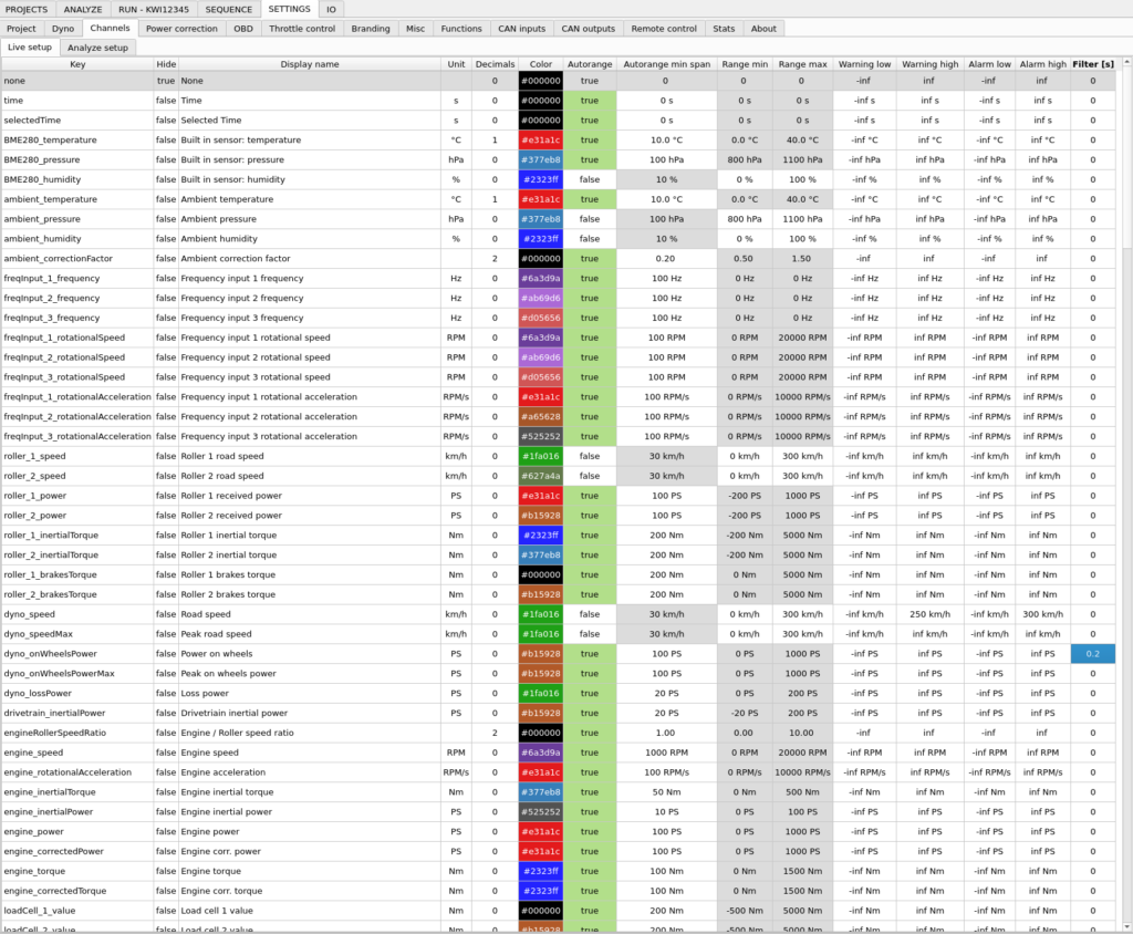
Live setup – configuration for channels displayed live in RUN tab
Analyze setup – configuration for channels in ANALYZE tab
This kind of division enables user to have different visualization settings during measurement and different afterward, when analyzing measurements.
Channel configuration can be accessed in Channels tab with double-click on channel, or directly from ANALYZE and RUN tabs through context menu functions in widgets displaying a channel.
By right-clicking the channels list, the configuration can be exported or imported from file.
Options that can be set for data channels have the following meaning:
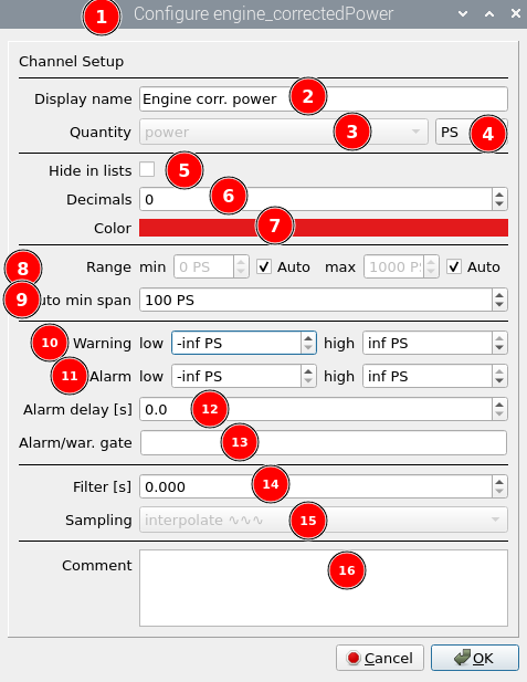
- Title bar with channel key name
- Changes channel label displayed in widgets. Every channel has an unchangeable key that identifies it and the name that can be changed according to user preferences or language.
- Physical quantity can’t be changed for built-in channels. It’s displayed here informatively. It can be set up for used added channels.
- Sets the channel display unit. It is only for display purposes. Data is processed always in SI units.
- Hides channel in lists. You can use this option to hide channels which are not used in your dyno or that are not important for you. These won’t be listed for selection in widgets.
- Decimal count for number display. Negative values switch to scientific notation display.
- Channel color. It is used by widgets in different ways. It can change plot axis labels color or number widget text color. Color is only used in RUN tab.
- Range options allow setting a fixed range border or automatic range setting to registered channel data.
- Autorange min span defines minimal range for widget scale. If i.e. analog channel has constant value 2.5V with some 0.01V noise it will scale from 2.49V to 2.51V and look very noisy. By setting min span to 1V, you can force it to scale automatically from 2V to 3V.
- Warning low and high value. If the channel value goes out of low-high range, it will be indicated by the widget that displays this channel.
- Alarm low and high value. If the channel value goes out of low-high range, the alarm will be displayed in the widget that displays this channel, on the statusbar. Optionally, the whole desktop can be highlighted, and alarm sound can be played.
- Delay from going over the alarm range to activating the alarm.
- Gate argument is an extra condition for checking warnings and alarms. For example, engine oil pressure channel can have a function that checks if the engine speed is over 100RPM as an alarm/warning gate.
- Low pass filter time constant for data display. Keep in mind that filtering channel with values above 0.1s will start to influence channel value visibly. If you filter engine torque characteristic that has short peak with 300Nm value, it can go down to 290Nm or even less. Higher time constant values also introduce visible delay on the signal in RUN tab. In ANALYZE the signal is zero-phase filtered, so there is no delay.
- Sampling type: Channels with “interpolate” option will be displayed with a straight line connecting samples. Channels with “sample and hold” option will hold the sample value until the new sample, transitioning to it with a sharp step.
- Comment with extra information about the channel. Useful for user created channels.
Notes on some quantities
- None quantity (-) is for channels that don’t have any quantity. It’s also the best choice if we don’t want to use unit system on a channel.
- fraction – a quantity useful for displaying ratios and fractions. For example, throttle opening percent.
- logic – a quantity that must be set, so the channel can be selected to be used as an ON/OFF (true/false) condition. For example, as a gate argument in other parts of the software.
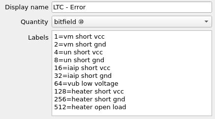
- bitfield – used to assign separate labels to every bit in the channel data. This may be used for a digital value containing some error flags. Any number of flags can be active at a time.
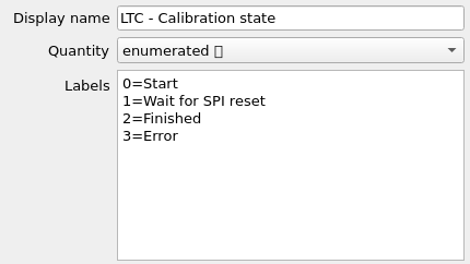
- enumerated – used to assign a separate label for every value of the channel. This may be used for a digital value that represents some state. Only one state can be active at a time.