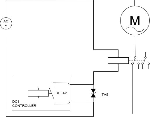
DC1 series controllers are equipped with mechanical relay outputs that can be used as a programmable switch to connect two wires. The logic controlling the relay can be freely programmed, so the relay can be activated with button press or for example when roller speed is greater than 20km/h.
The relay built in DC1 is rated to 250VAC and 16A resistive load.
Switching of highly inductive loads such as dyno fan motors or fume extractors is not allowed directly with the built-in relay and will lead to its damage after few switching cycles.
Big external loads should be switched with use of external contactor adequately rated for such load.
External contactors for heavy loads often are equipped with quite big coil that will create high voltage arcing on the DC1 internal relay contact. This arcing, if big enough, can disrupt DC1 operation.
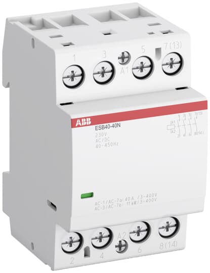
A good solution to the issue of voltage spikes created by the contactor coil is to use a contactor with build in circuit that suppresses the spikes. An example of a contactor with this function is ABB ESB series contactor.
Another way to counter disturbance from relay switching is to use TVS diode parallel to the relay. Example diode: 1.5KE400CA