Modbus in an interface standard that can be used to communicate with lots of industrial devices. Many devices can be connected to a single wire bus, they just need to have different addresses programmed. Available protocol allows both sending information and reading it, so you can meet both actuators and sensors using Modbus. A common device that can be connected to the dyno controller via Modbus is a VFD (Variable Frequency Drive). It usually provides both functions for writing information like the desired speed and reading information like bus voltage or power usage. The Modbus protocol’s versatility and compatibility make it an ideal choice for integrating the dyno controller with other industrial automation systems, empowering operators to streamline dyno operation.
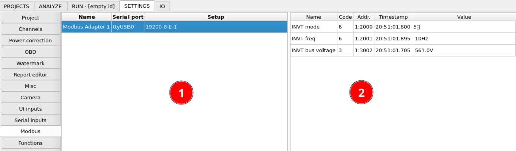
The left side of the configuration window contains Modbus interfaces configured in the system. Generally many devices can be connected to one interface, but in case you have some devices that can’t be reprogrammed to use the same bus parameters, you can use them on separate interfaces. After clicking the interface, you can edit functions assigned to it in the right part of the window. Relevant options to add and remove interface and functions are available under right-click.
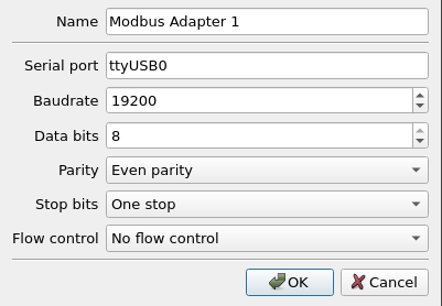
Modbus adapter setup contains bus setup options typical for setting up any serial port communication.
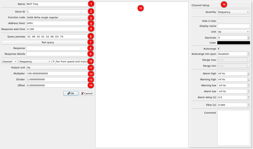
- Modbus function name
- Slave ID – this ID must be unique on all devices. You can change it in your slave device settings.
- Function code – standardized Modbus function code. Read slave device manual to get information which code you need to use to read or write the required information.
- 0x01 Read coils
- 0x02 Read discrete inputs
- 0x03 Read single register – common function for reading data from a register, for example sensor value
- 0x04 Read input registers
- 0x05 Write single coil
- 0x06 Write single register – common function for writing data to a register, for example VFD frequency setpoint
- Address (hex) – register address in hexadecimal format
- Response wait time – time the program waits before reading a response from the bus. It must be long enough for the slave device to respond to the query.
- Query preview – preview of bytes that will be sent on the bus with this function.
- Test query – press this button to test the query
- Response – plan hexadecimal response
- Response detail – interpretation of the response
- Data source setup for write functions – this can be any channel of constant
- Output unit – unit that the data is converted to for export from internal SI units
- Multiplier of output or input value
- Divider of output or input value
- Offset added to output or input value
- Preview of communication with the device
- Channel display setup
The output value is calculated the following way:
Output number = (Unit_Conversion(channel_value) + Offset) * Multiplier / Divider
If the function is set to input, the input value is calculated the following way:
Input value = Unit_Conversion(raw data number * Multiplier / Divider + Offset)