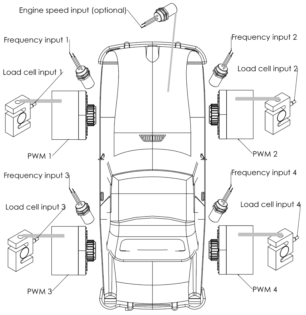
Sensors wiring
Wheels speed sensors – Frequency input 1 – 4
Brake torque sensors – according to the drawing – Load cell input 1 – 4
When there is no constant speed ratio between hubs and engine, an optional engine speed sensor can be connected to the Engine speed input.
Actuators wiring
For best performance, hub dyno should use BD3 brake interfaces. The interfaces are connected with single twisted pair CAN bus.
Software configuration
SETTINGS:
- General
- Dyno type – hub
- Loss from load factor – 0%
- Absorber dyno – checked
- Roller
- 1-4
- Vehicle wheel diameter – diameter for calculation of linear speed of vehicle. Does not take part in power calculation. Typically: 0.6m
- Speed source – frequency input
- Connected inertia – total inertia of bodies rotating at speed measured by the input. Mainly, it’s the absorber moment of inertia.
- 1-4
- Frequency Input
- 1 – 4
- Sensor type – shaft speed sensor
- Frequency low pass filter – usually 10Hz to 20Hz – filters speed fluctuations
- Frequency change low pass filter – usually 1Hz to 5Hz – filter for frequency time derivative – filters power resulting from acceleration of rotational inertia
- Signals per rotation – signal count per dyno shaft rotation
- Engine Speed – Parameters for optional engine speed sensor
- 1 – 4
- Load Cell
- 1 – 4
- Measures torque on – roller 1 – 4 – same as load cell number
- Gain, Offset – load cell calibration coefficients should be set with Wizard tool.
- Low pass filter – usually 1Hz to 5Hz. It’s best to set the same value as for associated Frequency Input / Frequency change low pass filter
- [unused load cell] / Measures torque on – none
- 1 – 4
- CAN bus – refer to BD3 Brake Power Supply specification and manual
- Torque control – required to use torque control mode. Also required for speed and acceleration control in standard controller architecture.
- 1-4
- Setpoint range – enter torque available from absorber – from PID controller point of view it’s better to enter torque that can be achieved most of the time, not the peak value.
- Setpoint source – speed / acc controller 1 – 4 output – same as torque control number
- Setpoint subtrahend – none
- Input filter frequency – enter maximum frequency that is sufficient to filter mechanical vibrations of the absorber. Too low frequency will slow down control speed. Typically, use values from 10Hz to 100Hz. Values low as the ones entered in Load Cell configuration are not required for the controller.
- kD filter frequency – filter for derivative PID part. Typically, use values from 1Hz to 20Hz.
- Zero output when SP==0 – check for faster brake discharging.
- Linearization function – function applied to PID controller output. For eddy current brakes, use x^(2/3).
- Speed correction – correction applied to PID controller output to compensate for absorber speed sensitivity characteristic.
- 1-4
Torque control, speed control and acceleration control require tuning according to guidelines presented on setting up control loops page.