Tool for calibrating a load cell is available in SETTINGS / Load Cell / Calibrate load cell
The following instruction was made on DC1 series controller where raw load cell value was in mV.
DC2 series raw value reading represents a fraction of excitation voltage that is measured on the load cell, which is a much smaller value than mV reading from DC1 series.
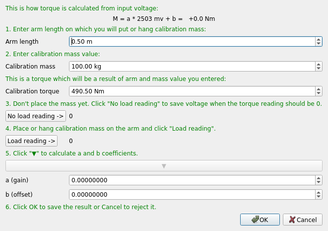
Calibration procedure:
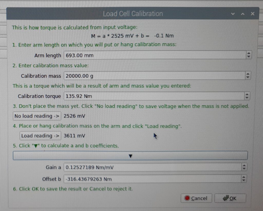
- Enter Arm length – horizontal distance from roller axis to calibration mass location.
- Enter Calibration mass – mass of the object that will be placed on the calibration arm.
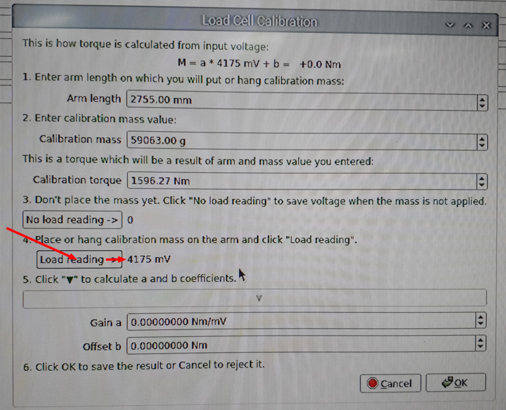
- Click No load reading ⇒ to acquire load cell voltage without any load placed (loaded only with dyno mechanism).
- Place the calibration weight on the arm.
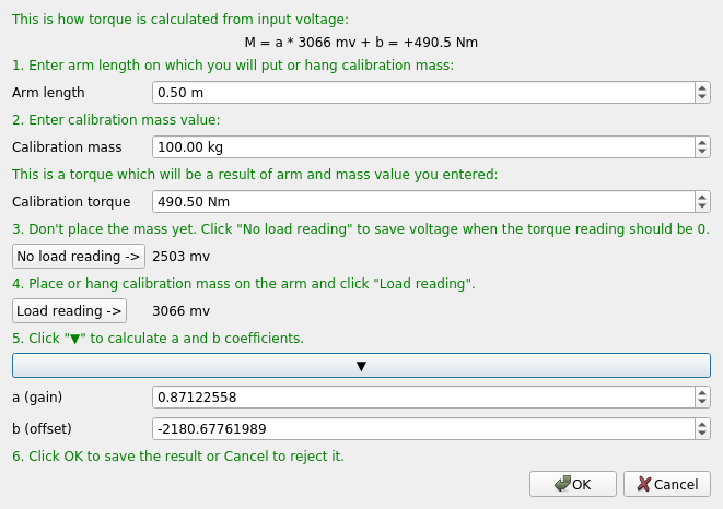
- Click Load reading ⇒ to get load cell voltage with known load.
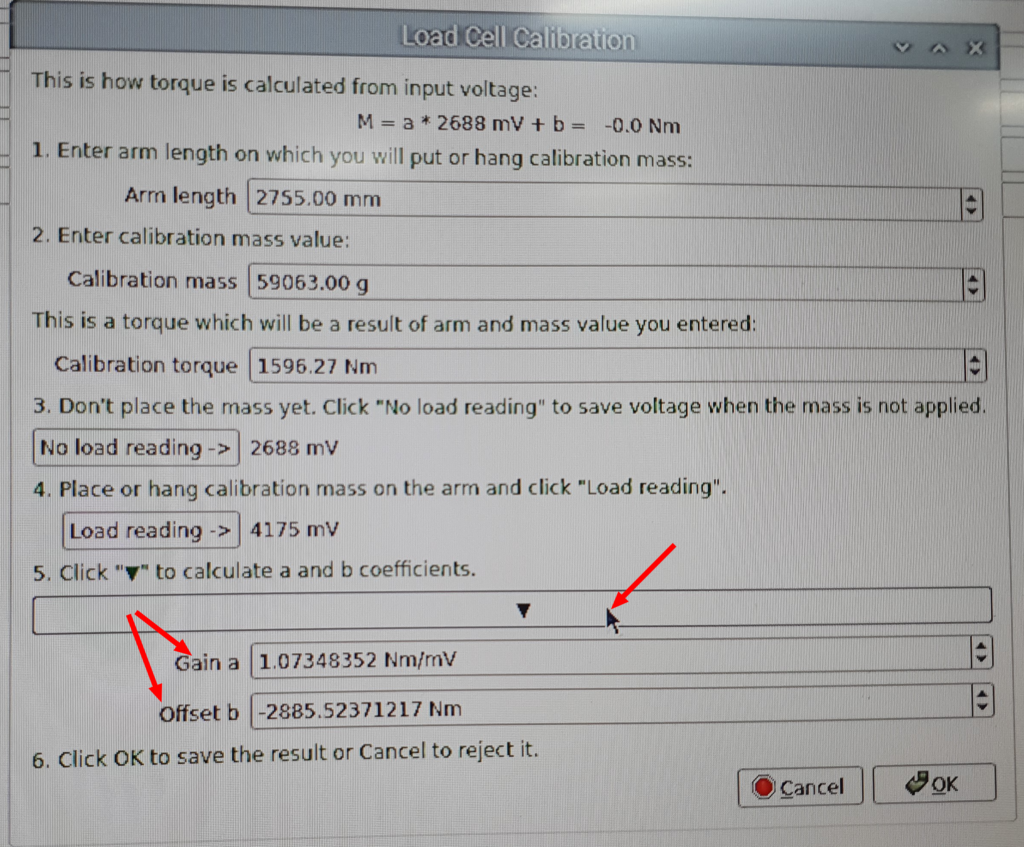
- Click ▼ to calculate load cell coefficients.
- Coefficient can be verified by checking the equation at the top of the tool window.
Example calibration procedure with use of detachable torque arm on a Dynocom dyno
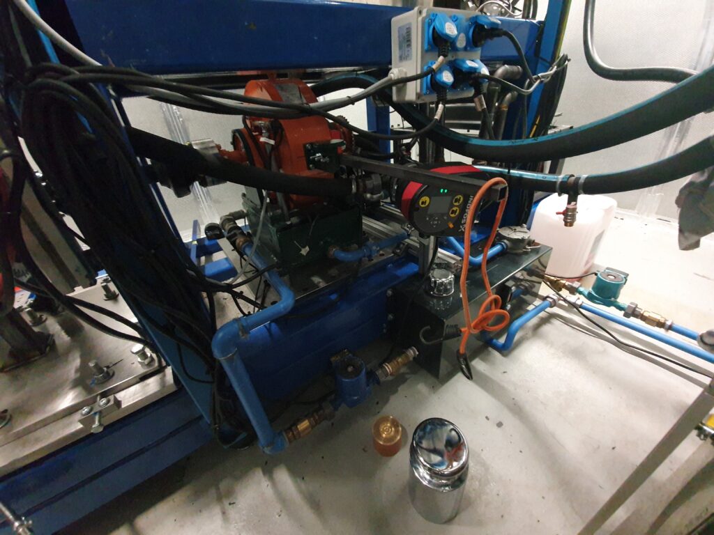
Step 1
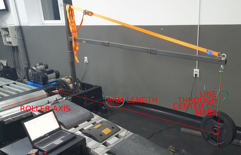
Prepare the arm that will be used to generate calibration torque. The arm must be attached to the absorber (brake) body. Notice that the rope with unknown mass that will be used to hang the known mass is already in its place.
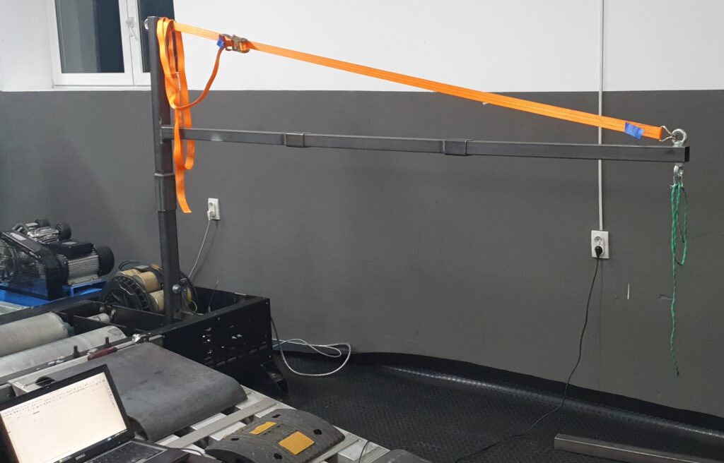
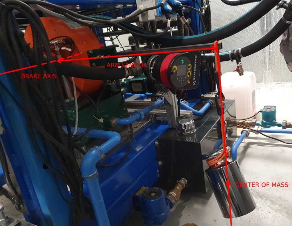
Step 2
Hang the known mass on the arm and measure arm length.
The vertical position of the mass is not important. It can be above or below the roller axis, too.
When measuring the arm length, it is important to make the measurement across a horizontal line, perpendicular to the roller axis.
The center of mass will always be passed through by the line created by a single rope that is used to hang the mass. This fact is a bit obscured in the above picture by use of two ropes and picture perspective.
Step 3
Note: The order of steps 1 and 2 can be interchanged.
In step 3 the tool is used to calculate the gain and offset of the calibration. Then the OK button is pressed to apply new settings.
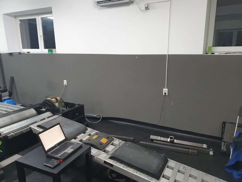
Step 4
Step 4 is only required when the arm used to create the torque will be removed after calibration. In this case, it is obvious, but some dynos have some permanently installed arms for the purpose of calibration.
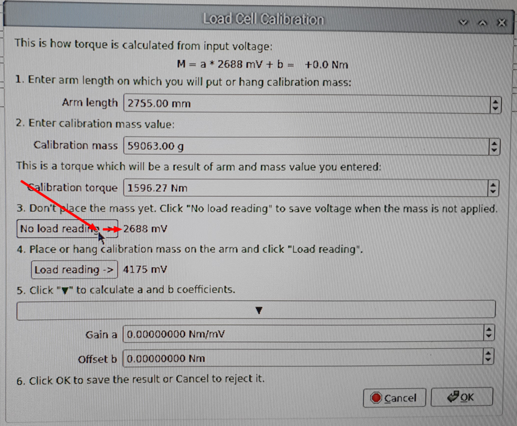
Example calibration on engine dyno
Here is another calibration example made on engine dyno.
Some final comments on the dyno calibration
The eddy current brake was equipped with a shelf that was designed for load cell calibration. I decided not to use the shelf and add an extension steel bar because of two reasons:
-When the mass is placed on the shelf, it’s harder to precisely know where the center of mass is in relation to the brake axis. If it’s hanged, we can measure distance from axis to the vertical rope used to hang it.
-The shelf was around 260mm from the brake axis and the extended arm was at 693mm. If I assume that my torque arm length measurement have a fixed error of 1mm in both cases, then with use of the 260mm arm the error is 1mm/260mm = 0.38% and in case of extended 693mm arm it is 1mm/683mm = 0.15%
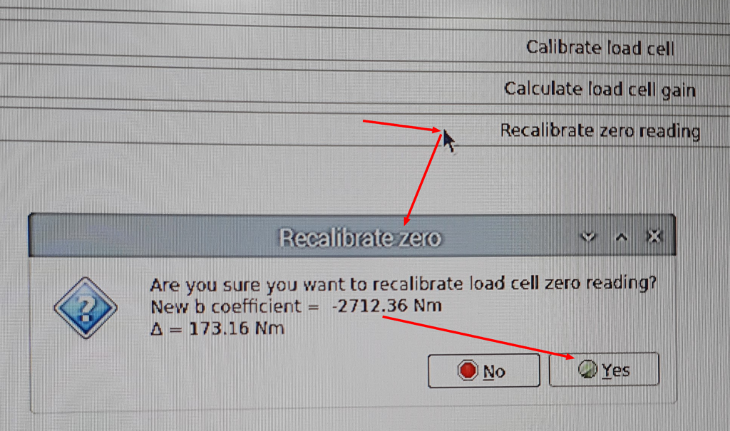
After the calibration, the extended bar was removed and the zero reading was recalibrated.
Be sure to precisely know the mass of the load. In the case of the engine dyno I had a professional 20kg calibration weight that has 1g tolerance. In the case of Dynocom dyno I used much cheaper weights from the gym, but I had these precisely measured. As it turned out, all my “20kg” weights from the gym have real mass in the range 19.68kg to 19.69kg. That would be 1.6% error if I just assumed these are real 20kg. Don’t trust your bathroom scale with the measurement. It can easily be a few percent off. Also don’t trust your bathroom scale specification, it often confuses the scale resolution with its accuracy. A good idea is to ask for a favor at a post office or even a grocery store. The scales used in commercial trade are required by law to have accuracy around 0.1% and to be calibrated every few years.
Use calibration torque adequate to the range you will be using. If you have a 1000Nm absorber, and you create 1000Nm during the calibration, that’s perfect. If you create 200Nm, that’s still reasonable. If you create only 10Nm, the calibration result will not be reliable.