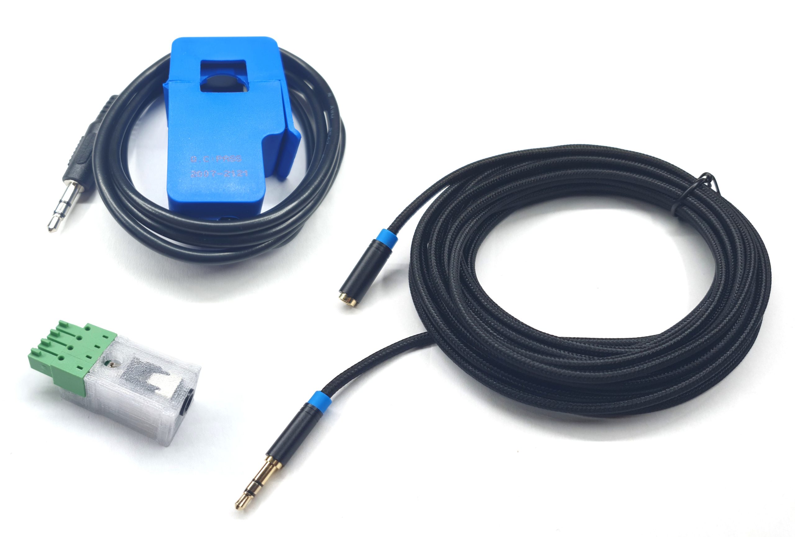
Engine speed information is required to calculate engine torque and to plot the right RPM scale on dyno report. There are some situations where engine speed doesn’t have constant relation with dyno speed and it cannot be calculated with simple ratio and OBD interface is not available. To get correct engine speed reading in these situations, the controller is equipped with specialized Engine speed input, that allows direct readout of the engine speed. The following sensors can be connected to this input:
Variable reluctance sensor, VR sensor
| +12V / +5V | |
| SIG+ | First VR sensor wire |
| SIG- | Second VR sensor wire |
| GND- |
Hall type sensor or other digital signal
| +12V / +5V | Sensor power supply |
| SIG+ | Sensor signal |
| SIG- | Reference voltage (must be between 0V and 4.5V) |
| GND- | Sensor return ground |
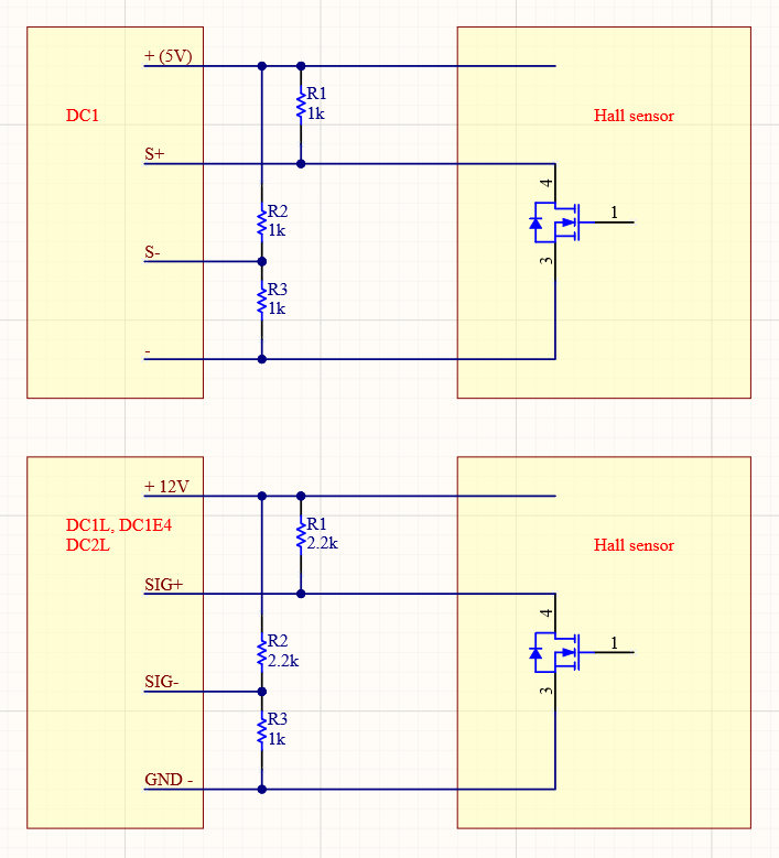
When hall type sensor is used, it is required to connect some external resistors. R1 is usually required for sensors with open collector output. R2 and R3 create a voltage divider that supply a reference voltage to S- input.
Injector, ignition coil
| +12V / +5V | Voltage divider supply |
| SIG+ | Ignition or injector signal |
| SIG- | Reference voltage (must be between 0V and 4.5V) |
| GND- | Sensor return ground |
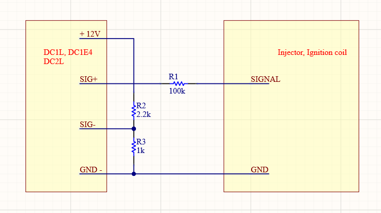
In case of signal from ignition coil low voltage side, it is required to add an extra R1 resistor in series to protect the controller from high voltage spike.
PEREK PES1 photoelectric sensor
The photoelectric sensor has the same output and connection as mentioned above hall sensor. It can be used with a bright marker placed on a part rotating in sync with the engine.
PEREK CS1/CS2 clamp inductive sensor
CS1/CS2 is an inductive sensor designed to read engine speed signal from ignition coil wires (high or low voltage).
| +12V / +5V | Sensor power supply | White wire |
| SIG+ | Sensor signal | Green wire |
| SIG- | Reference voltage | Brown wire |
| GND- | Sensor return ground | Brown wire |
Any sensor different from mentioned above
| +12V / +5V | Power supply output to be used by the sensor or reference voltage divider |
| SIG+ | Input signal |
| SIG- | Reference voltage input (must be between 0V and 4.5V) |
| GND- | Return ground for sensor or voltage divider |
Many sensors not mentioned above could be connected to the Engine speed input. Input circuit analyzes voltage between S+ and S- terminals. The speed signal is triggered when S+ potential drops below S- potential. Circuit rearm voltage is set to 30% of S+/S- peak voltage. When the rearm voltage is crossed, the circuit gets armed to generate the next speed signal.
After a typical 85ms (45ms – 140ms) timeout, the adaptive arming threshold is reset to 30mV.
To connect any sensor, a circuit must be created which ensures that S+ potential will drop below S- potential every time that speed signal generation is required. If a fixed S- reference is used, it must be between 0V and 4.5V.
A custom reference voltage strategy can be implemented by connecting the engine speed input S- pin to the analog output S pin, and programming the analog output to provide the voltage calculated by your strategy.
Measurement methodology
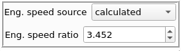
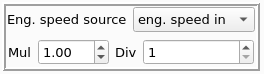
The primary way to make measurement using the signal on the Engine speed input is to select eng. speed in as a source of engine speed and set signal multiplier and divider based on used signal source.
| Signal source | Multiplier | Divider |
|---|---|---|
| Photoelectric sensor with marker on crankshaft or pickup on ignition coil in wasted spark configuration or any configuration with one signal per engine revolution | 1 | 1 |
| Photoelectric sensor with marker on camshaft or pickup on ignition coil in full sequence ignition or pickup on injector wire in full sequence injection or any configuration with one signal per 4 stroke engine cycle | 2 | 1 |
| Signal borrowed from engine trigger wheel | 1 | number of teeth per crankshaft revolution 60-2 wheel -> divider = 58 36-1 wheel -> divider = 35 |
| Photoelectric sensor with marker on vehicle wheel | Calculate multiplier from gearbox and final gear ratios | 1 |
Sometimes the engine speed signal source doesn’t give a good signal in the whole range of engine speeds, or the signal is missing on coastdown. This can be a common case with signal sourced from ignition coils. The faulty signal will corrupt the measurement when it occurs. To make measurement in this case, first we need to use eng. speed in option when the signal is clear and correct. Next we switch the source to calculated option. The software automatically sets the calculated speed ratio from the one that was present before mode switching. The measurement is made with calculated option.