Configuration for BD1 power supply and eddy current brake:
- Mode – duty cycle modulation
- Source – torque controller n output
- Frequency – 2000Hz
- Min duty cycle – 0%
- Max duty cycle – maximum braking force percent
For water brake with ON / OFF type water valve frequency should be lower:
- Frequency – 2Hz
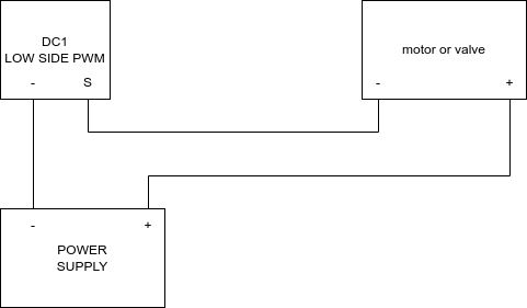
Connection schematic for devices requiring external power supply
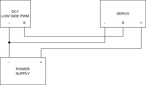
RC servo wiring diagram
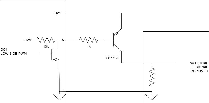
Signal inversion for receiver requiring high side signal
Using internal power supply for low power devices

DC2 bidirectional DC motor control – one supply, two bridges
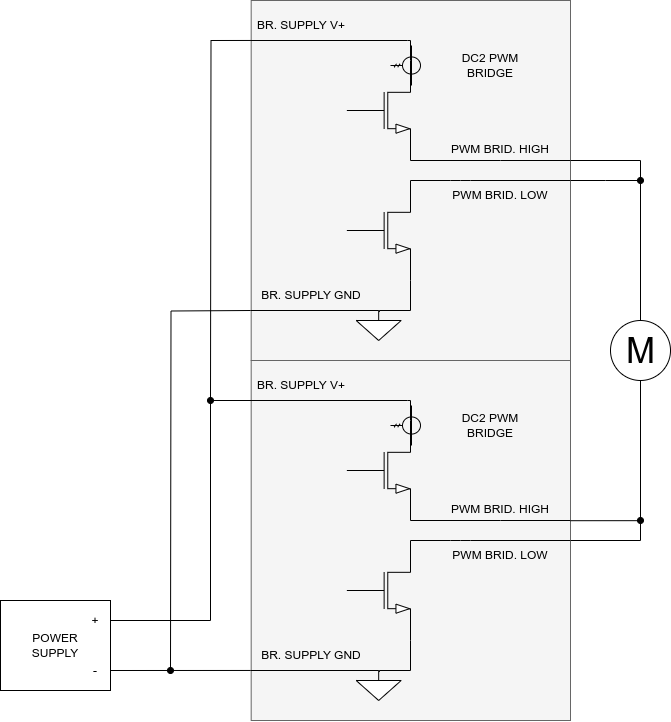
Example configuration for actuator control in both directions:
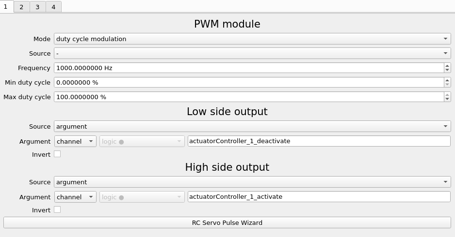
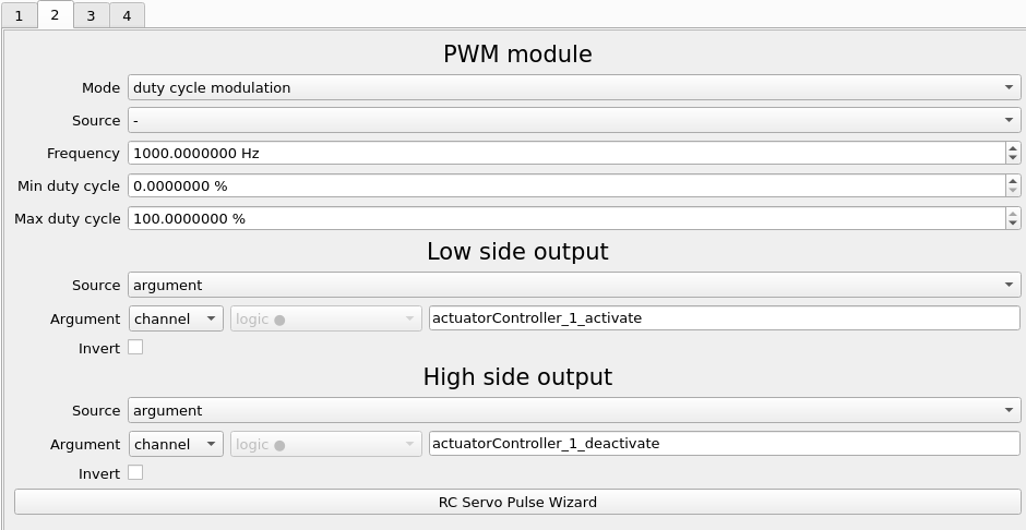
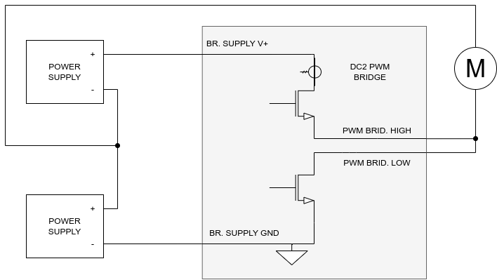
DC2 bidirectional DC motor control – two supplies, one bridge
This configuration allows controlling DC motor in two directions with use of only one PWM half bridge in DC2 per motor. This way you can control up to 4 motors from one DC2 controller.
‘-‘ in the top supply must not have a connection with ‘-‘ in the bottom supply to avoid short circuit.
Total bridge supply voltage must not exceed 28V.
Remember that current measurement is available on the high side of the bridge, so turning off the motor based on current will be available only in one motor direction.
