Device description and supported dynamometers
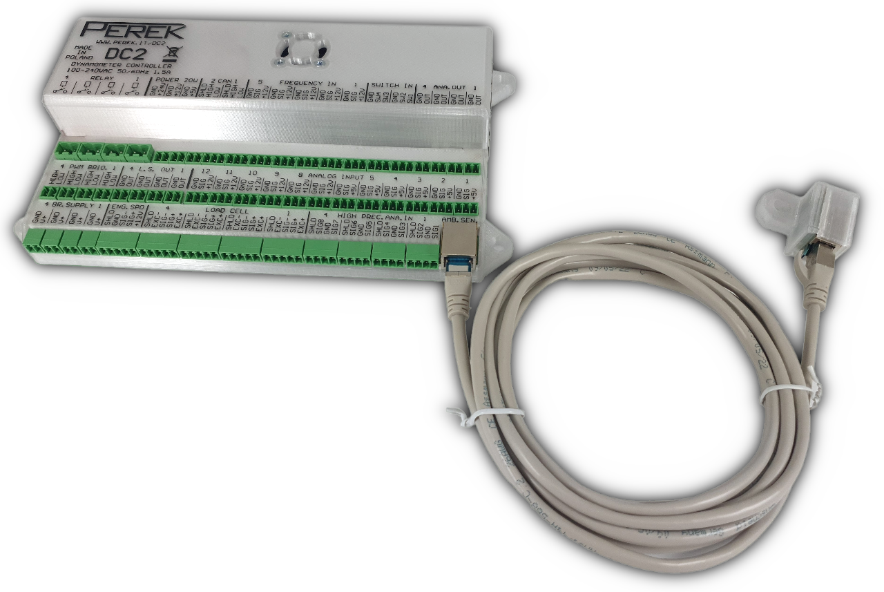
DC2 series Dyno Controllers are a versatile solution designed to control multiple types of dynamometers. It’s compatible with hub, engine and chassis dynos, and it works with multiple types of dyno absorbers. DC2 series contains the following models:
- DC2 – top of the range, upgraded version of DC1E4
- DC2L – budget controller for simple dynamometers that don’t require all DC2 features
Main upgrades from DC1 series controllers:
- More inputs, more outputs, bigger data memory, faster CPU
- New high side outputs with current measurement for bidirectional DC motor control
- High precision load cell inputs with built-in programmable amplifier that support direct load cell connection
- Weather station moved to a separate enclosure and connected with a cable to the main controller
| Feature | DC2L | DC2 |
|---|---|---|
| RAM memory | 4GB | 8GB |
| Internal data memory | 64GB | 256GB |
| CAN-BUS lines | 1 | 2 |
| Power outputs | 5V, 12V only for sensor inputs 10W total | 5V, 12V, 24V for sensors and on separate connectors 20W total |
| Analog outputs | 1 | 4 |
| Low side PWM outputs | 2 | 4 |
| High side PWM outputs | 0 | 4 |
| ON / OFF low side outputs | 1 | 4 |
| Relay outputs | 1 | 4 |
| Frequency inputs | 1 | 5 |
| Multi sensor, engine speed frequency input | 1 | 1 |
| Load cell inputs | 1 | 4 |
| 0-5V fast analog inputs | 1 | 12 |
| High precision 0-5V analog inputs with thermocouple support | 4 | 8 |
| Switch inputs | 1 | 4 |
| Supported dynamometer configurations | Inertial or absorption dyno Engine dyno Motorcycle dyno 2WD chassis dyno 4WD chassis dyno with mechanical synchronization | Inertial or absorption dyno (up to 4 absorption units) Engine dyno Motorcycle dyno 2WD chassis dyno 4WD chassis dyno with mechanical synchronization 4WD chassis dyno without mechanical synchronization 2WD hub dyno 4WD hub dyno |
The controller is an all-in-one device, that combines PC type computer with operating system and dedicated software, and microcontroller system to control dyno and acquire data in real time.
Tasks performed by the controller:
- Readout of dyno parameters and data logging signals from additional sensors and OBD
- Generation of absorbers control signal
- Control of auxiliary dyno devices such as fans etc.
- Saving of all the data and later analysis
- Option to extend controller capabilities with CAN-Bus connected devices.
DC2 can make use of any absorber system that can be controlled with:
- Digital PWM signal
- Direct PWM control with current up to 3A
- 0-10V analog signal
- CAN bus message
Most popular absorption units are:
- Eddy current absorber – fast and affordable
- Water cooled eddy current absorber – fast and suitable for long-term tests on high load
- Water brake absorber – slow but capable of high torque for long time tests
Note on modern traction control and axis synchronization:
The DC2 uses connected absorbers to synchronize speed on all vehicle wheels, however modern Traction Control systems are so sensitive to any speed difference that the best way to be sure that TC is not activated is to use mechanical axle synchronization. The AC motors synchronizing speed on axles is another solution, but it is expensive and not tested with DC2 yet.
Safety precautions
- The device should be fixed on a hard, flat surface in a well-ventilated area.
- The device must not be exposed to vibration.
- The device air flow must not be obstructed.
- No foreign objects should be inserted into the device.
- Life-threatening, high voltages are present in the device. Make sure that it is disconnected from mains power supply before doing maintenance work.
- The device is intended for installation by qualified personnel.
- The device must be installed in a closable electrical cabinet and protected from access by unskilled personnel.
- The device should be protected from moisture. It mustn’t be used when wet.
- The device should be protected from ingress of conductive contaminants. It shouldn’t be operated where metal grinding or cutting dust is present in the air.
- The device mustn’t be powered without the enclosure assembled.
- The device installation doesn’t require enclosure disassembly.
- If the device is not working correctly, makes disturbing noises, emits burning smell, it should be immediately powered down. Please contact the manufacturer for repair.
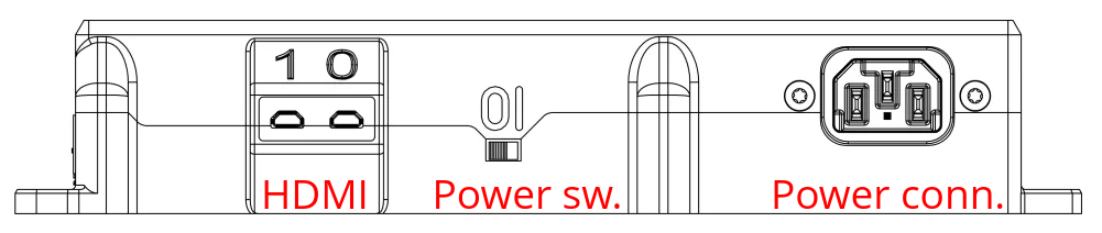
- The device power supply must be protected with 2Amp circuit breaker.
- The device must be connected to an earthed mains socket-outlet
General specification
| Power supply | 100-240 VAC, 50-60Hz, 1.5A, IEC C14 socket |
| Ambient temperature | −20°C – 50°C |
| Ambient humidity | 0%-95% non condensing |
| Elevation | Up to 2000 m.a.s.l. |
| Base computer | 4-core Cortex A76 2.4GHz 4/8GB RAM LPDDR4 Data memory 64/256GB 100MB/s |
| Microcontroller | 32-bit RISC 64MHz |
Inputs / outputs
- Wi-Fi IEEE 802.11b/g/n/ac (2,4/5 GHz)
- Bluetooth 5.0 (Low Energy (BLE))
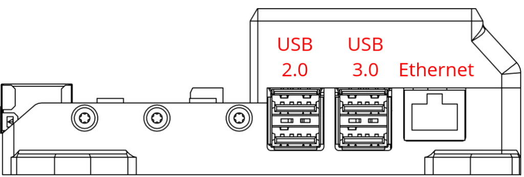
- Gigabit Ethernet
- 2 x USB 2.0
- 2 x USB 3.0
- 2 x micro HDMI
- Ambient condition sensor / weather station (temperature, pressure, humidity) included as a separate device
- CAN-BUS 2.0B
- Power outputs 24V, 12V, 5V
- Analog outputs 0-10V
- Low side PWM outputs 3A 40V
- High side PWM outputs 3A 28V with current measurement
- Additional ON/OFF low side outputs 3A 40V
- Two-terminal relay outputs 250V 16A
- Frequency inputs for axle speed or other sensors with frequency signal up to 10Mhz
- Engine speed input for hall, VR, inductive or capacitive clamp sensors up to 15kHz
- Dedicated load cell inputs with integrated programmable amplifier
- Fast, general purpose analog inputs 0-5V
- High-precision analog inputs 0-5V for thermocouples or other analog signals
- 2-pin switch inputs
PC typical interfaces
The controller is equipped with typical interfaces, found in PC type computers, such as USB, Ethernet, micro HDMI. These allow to connect standard input / output devices such as mouse, keyboard, printer, display and internet connection. Wireless interfaces such as Wi-Fi and Bluetooth are also available.
Bluetooth enables wireless connection with vehicle OBD system, for readout of engine parameters, with use of optional interface. If single display is used it can be plugged in either in HDMI port 0 or 1.
RJ45 port for Ethernet connection is located next to the USB ports. Take care not to plug Ethernet network cable to the Ambient Sensor port, which uses RJ45 connector too.
Ambient sensor and power correction
The weather station shipped with the controller has a precise Bosch ambient sensor that is used to measure temperature, pressure and humidity which can be used to calculate engine power correction. Available correction standards are:
- DIN 70020
- EC 95-1
- ISO 1585
- JIS D1001
- SAE J1349
- EEC 80/1269
- SAE J607
- FOS
Sensor specification:
- Humidity: 0% ÷ 100% ±3%
- Pressure: 300 ÷ 1100hPa ±1.7hPa
- Temperature: -40 ÷ 85°C ±1.25°C
The ambient sensor should be connected with supplied shielded RJ45 cable to the designated port in the controller.
The Ambient Sensor port must not be connected to the Ethernet network. Connecting it to a network with a POE function will cause instant damage to the device.
All power correction parameters can also be sourced from any data channel available in the controller. For example:
- external sensor connected to analog input
- OBD
- CAN bus
CAN-Bus interface
The controller is equipped with CAN-Bus 2.0B transceivers, with transmission speed up to 1Mbps, compatible with ISO-11898-2 and ISO-11898-5.
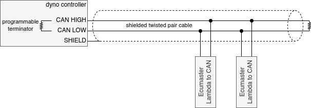
Inside the controller there is a software controlled 120Ohm terminating resistor for each bus.
CAN-Bus is routed with one twisted pair of wires and allows connecting many devices in parallel on one bus.
The interface is NOT isolated. The device you are connecting must be on to the same ground reference as the dyno controller, or the driver will be damaged.
The maximum allowed DC voltage on CAN HIGH and CAN LOW terminals is -58V to +58V.
For maximum interference immunity a shielded twisted pair cable should be used.
Example devices that can connected to the controller via CAN-Bus:
- Additional actuator drivers, H-bridges for servo motor control
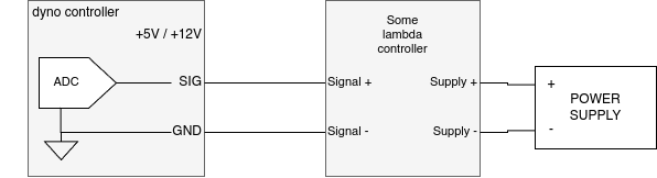
- Additional input extenders – wideband oxygen sensor controller, extra analog inputs
- Automotive displays such as Ecumaster ADU
- Engine control units such as Ecumaster EMU Black, which can be used to read engine operation parameters or to control throttle opening
Power supply outputs
DC2:
- 3 separate power supply outputs: 24V, 12V, 5V (2A), capable of total 20W power
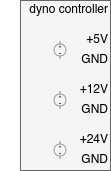
DC2L:
- 12V and 5V is supplied only to sensor connectors with total 10W power.
- 12V power: 9W
- 5V power: 1W
Low power external modules can be connected to the supply.
The supply can be used to power external relays and control them with low or high side outputs.
USB
Up to 1A total can be used from USB ports. If you have devices that need more, use external USB hub that has a separate power supply.
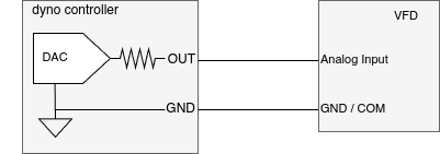
Analog outputs
- Analog outputs with 0-10V range are intended to control auxiliary dyno devices requiring analog signal.
- Can be used to control dyno absorber in retrofit applications.
- Output impedance: 1kOhm
- Resolution: 12bit
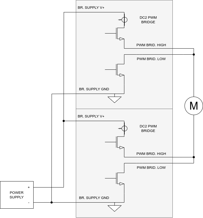
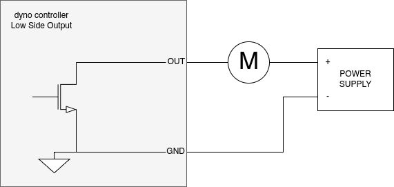
Low side, high side and relay outputs
The controller is equipped with low side outputs, capable of connecting terminal to ground and high side outputs to supply voltage.
- Maximum switched voltage low side: 40V
- Maximum switched voltage high side: 28V
- Maximum current: 3A continuous, 12A peak
- Maximum inductive load switching energy: 50mJ
- Short circuit and overload protected
- Short circuit and overload protected
Part of the outputs have hardware PWM generation functionality and can generate PWM signal with frequency from 0.06Hz to 50kHz and resolution of 20bit. PWM outputs are capable of controlling:
- eddy current brakes (with use of external BD1 brake power supply)
- solenoid valves
- servo motors compatible with RC pulse signal
- power modulation of devices such as cooling fans etc.
Low side and high side outputs can be joined into half or full bridge to enable bidirectional control of DC motors.
High side outputs have current measurement functionality.
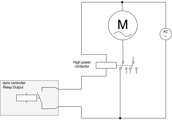
Remaining low side outputs and relay outputs are controlled with programmable logic and allow to power auxiliary devices according to operating conditions or user input. Example use cases are:
- automatic fan turn on above preset engine speed
- starter motor control from dyno keyboard
Relay output capacity is 250V 16A for resistive load. Switching high inductive load may require an external arc suppression circuit.
Frequency inputs
Inputs specification
- Maximum input signal voltage: 15V
- Signal threshold voltage: 2.5V
- Hysteresis: 0.6 – 1.2V
- Pulse capture mode frequency range: 15mHz – 15kHz
- Pulse capture mode resolution: 31.25ns
- Pulse capture mode accuracy: 0.003%
- Pulse capture mode precision @ 1kHz: 0.0032%
- Pulse capture mode precision @ 15kHz: 0.045%
- Pulse count mode frequency range: 10kHz – 10Mhz
- Pulse count mode sampling frequency: 1000Hz
- Pulse count mode accuracy: 0.003%
- Pulse count mode precision = Sampling frequency / Input frequency
- Pulse count mode precision @1MHz: 0.1%
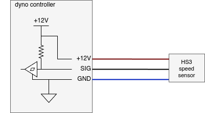
The engine speed input allows reading signal from Hall, VR, inductive or capacitive clamp sensors. It can be used to read engine speed in cases where the speed is not in constant relation with dyno roller or shaft speed.
- Input voltage up to 50VAC sine, 250V peak
- Differential input
- Adaptive signal arming threshold from 23Hz up
- Pulse capture mode frequency range: 15mHz – 15kHz
- Pulse capture mode resolution: 31.25ns
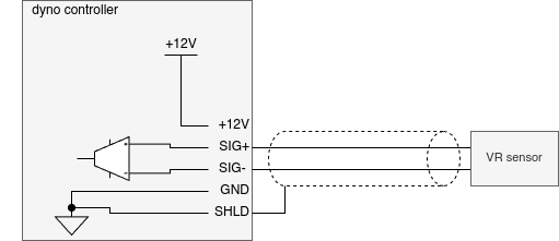
Some other examples of engine speed input connections.
In DC2L controller the shield wire should be connected to GND.
Load cell inputs
The controller has dedicated, differential high precision inputs with built-in programmable amplifier for direct connection of load cells.
A shielded cable must be used for load cell connection.
- Excitation voltage: 5V
- Amplification range: 1 – 128
- Differential voltage range: 4V
- Voltage on inputs for measurement: 0.5V – 4.5V
- Allowable voltage on inputs: 0V – 5V
- Resolution: 24bit
- Logging frequency: 500Hz
- Sampling frequency: 256kHz
- Measurement accuracy: 0.06% @ 0°C ÷ 40°C
- Measurement precision: 0.04% @ 0°C ÷ 40°C
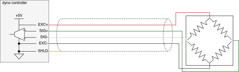
In DC2L controller the shield wire should be connected to EXC-.
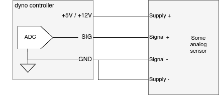
Analog inputs
The device has analog inputs with 0-5V range that can be used to connect any additional sensor.
DC2 has 6 analog inputs with +5V supply pin and another 6 inputs with +12V supply pin. All of these 12 inputs have 0-5V input signal range.
- Maximum input voltage: 30V
- Measurement range: 0-5V
- Resolution: 14bit (1mV)
- Logging frequency: 500Hz
- Sampling frequency: 25kHz
- Measurement accuracy: 1% @ 0°C ÷ 40°C
- Measurement precision: 0.3% @ 0°C ÷ 40°C
High-precision analog inputs
The device has differential pairs of high precision analog inputs. These inputs can be used for direct thermocouple connection or for connection of any sensor giving signal in 0-5V range. Every pair allows measuring one signal in differential or two signals single-ended mode.
| DC2L | DC2 | |
|---|---|---|
| Maximum differential signals | 2 | 4 |
| Maximum single ended signals | 4 | 8 |
- Resolution: 16bit (3.9μV – 94μV)
- Logging frequency: 10Hz
- Sampling frequency: 250kHz
- Voltage ranges: 0-256mV to 0-5V
- Measurement accuracy: 0.16% @ 0°C ÷ 40°C
- Measurement precision: 0.1% @ 0°C ÷ 40°C
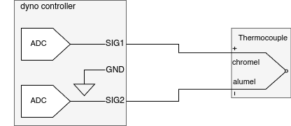
K-Type thermocouple connection:
Differential (above and below ambient temperature measurement):
alumel (-) to S2
chromel (+) to S1
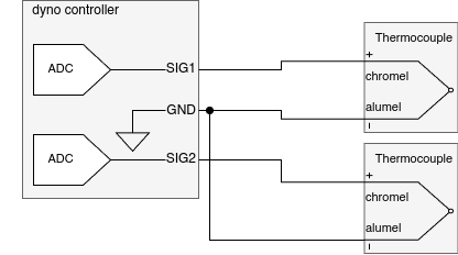
Single ended (only above ambient temperature measurement):
alumel (-) to –
chromel (+) to S1 or to S2 for second sensor
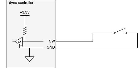
Switch inputs
The device has inputs for switch connection. A switch can be used to activate software functions or controller outputs.
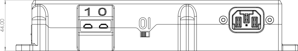
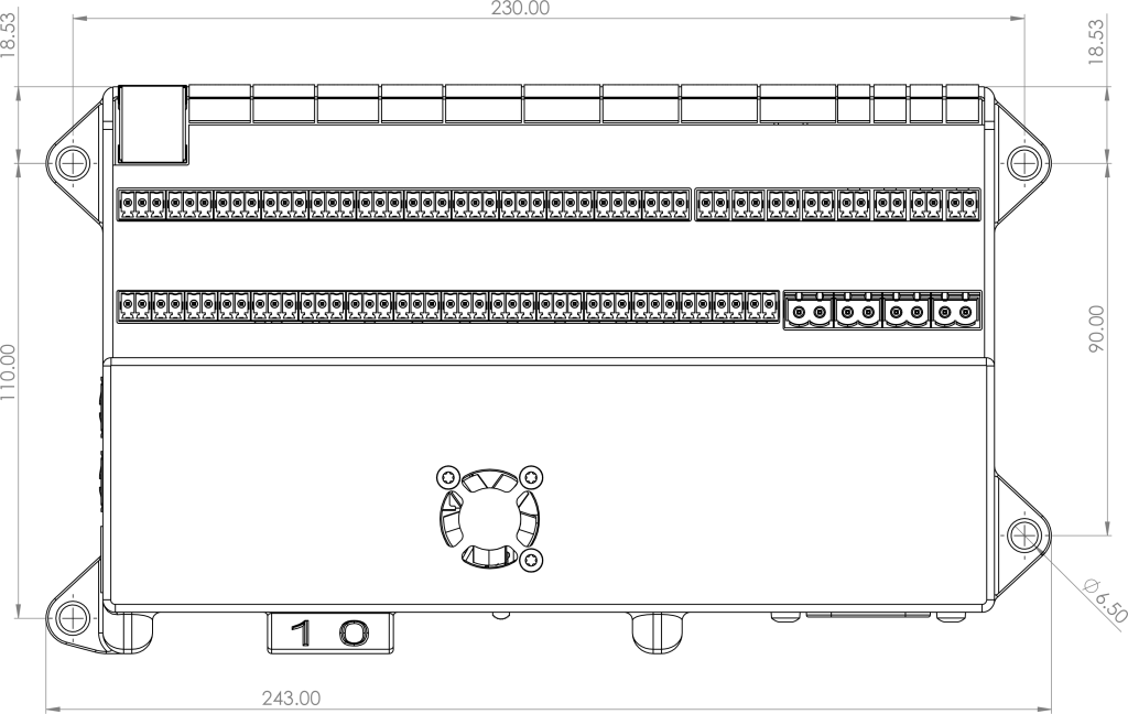
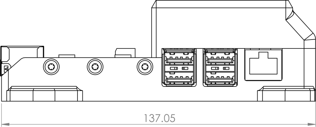
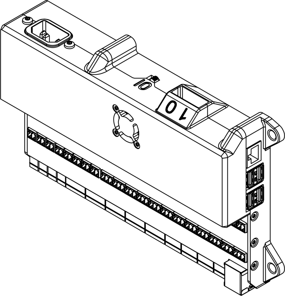
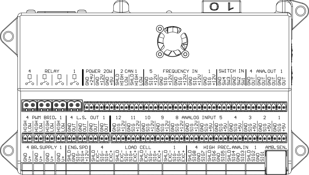
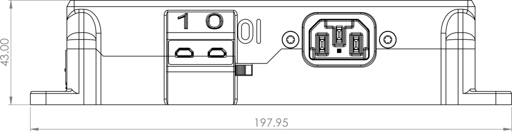
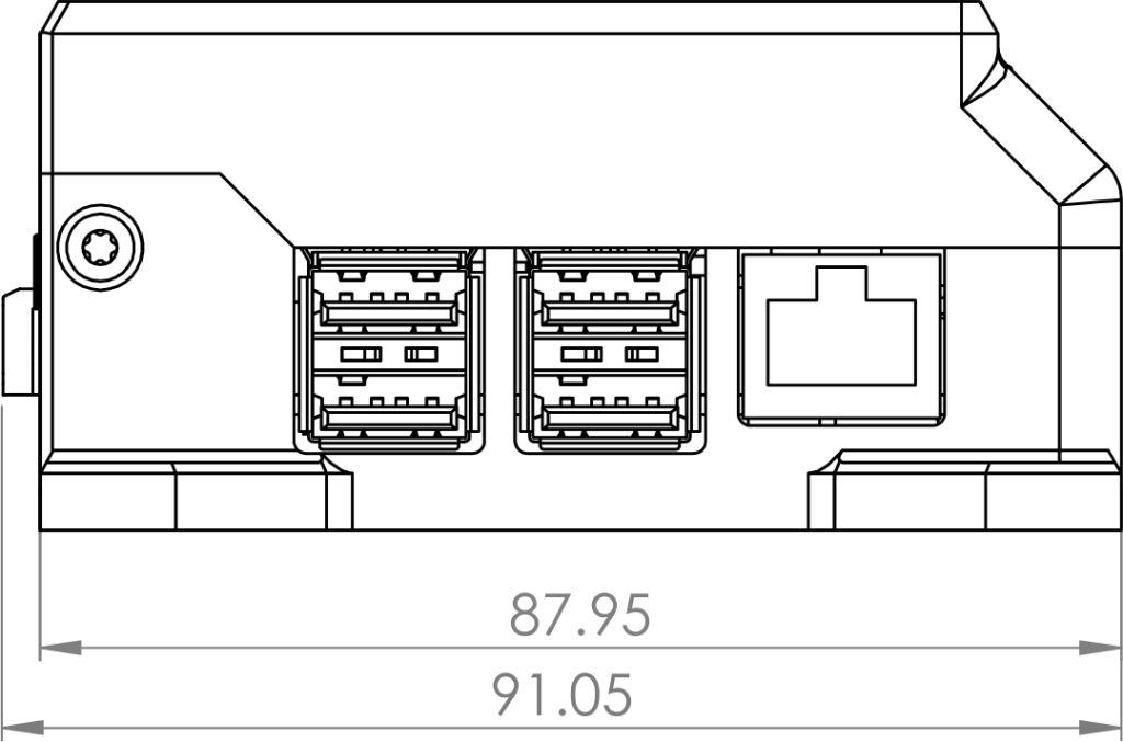
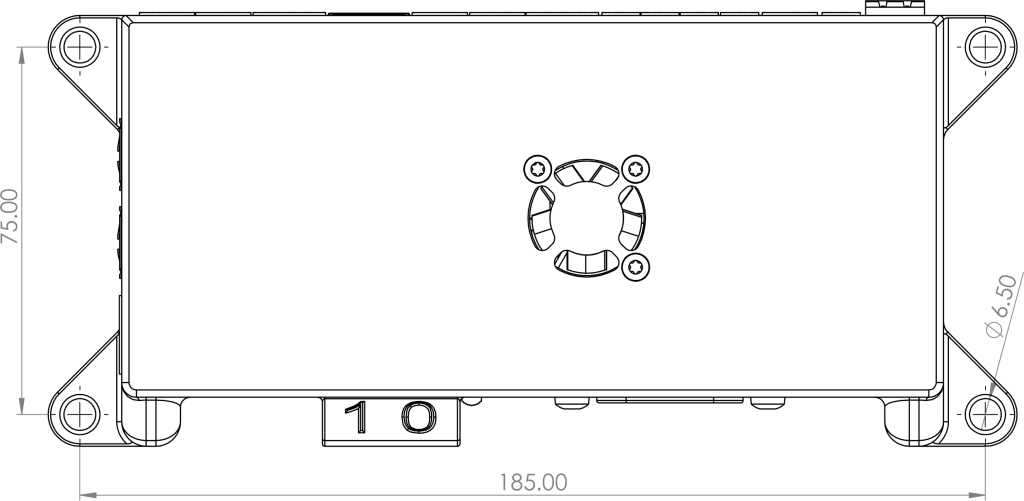
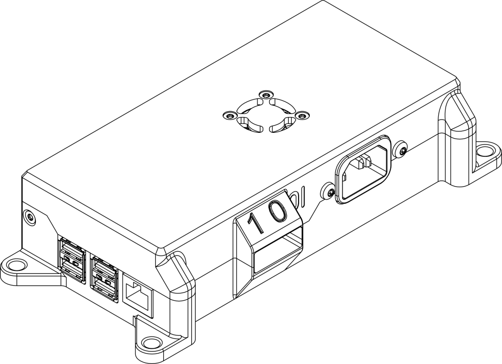
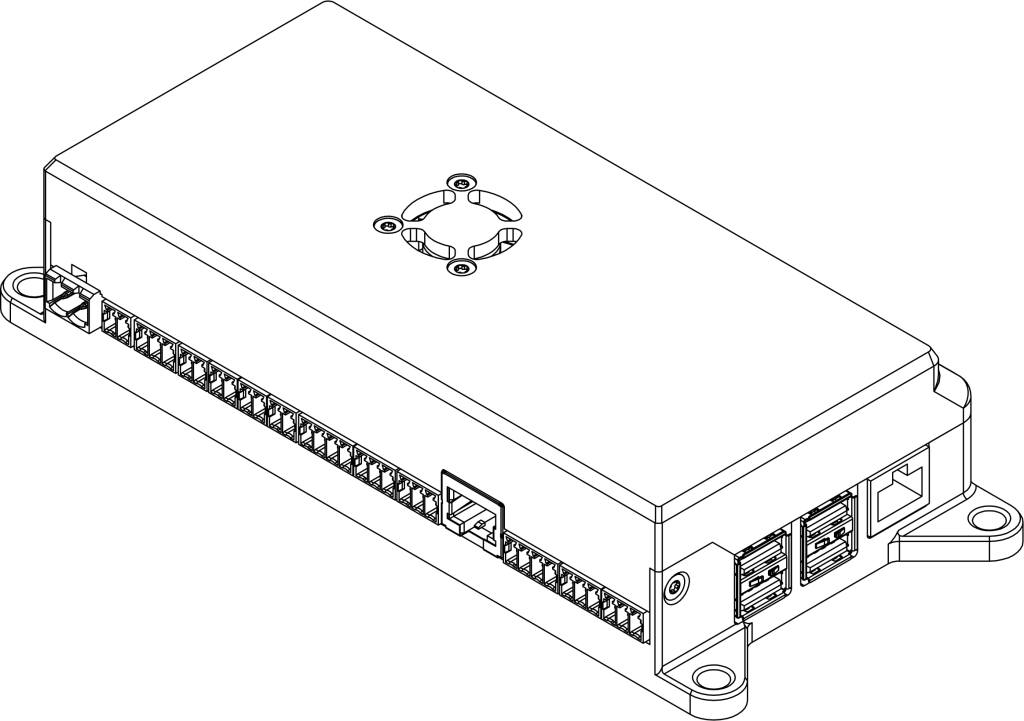
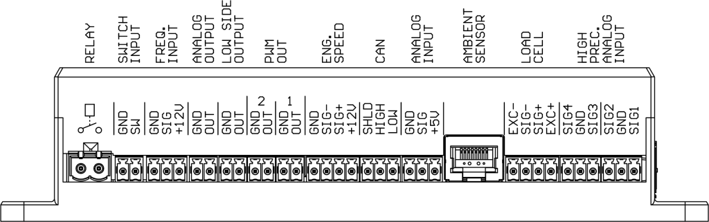
Technical drawings and pinout DC2
Technical drawings DC2L
Warranty
The producer guarantees that the device is manufactured according to accepted craftsmanship practices, and it meets the applicable standards. Correct device operation is guaranteed for 24-month period starting from date of purchase.
The guarantee does not cover damages caused by improper installation, usage or non-compliance with the instruction manual.
The device is intended for installation by qualified personnel. Device final performance and suitability for a particular application is dependent on the user, and thus it is not guaranteed by the manufacturer.
These specifications are subject to change without notice.
FCC
This device complies with part 15 of the FCC Rules. Operation is subject to the following two conditions:
- This device may not cause harmful interference.
- This device must accept any interference received, including interference that may cause undesired operation.
Contains TX FCC ID: 2ABCB-RPI5
Contains IC: 20953-RPI5