Variable Frequency Drive (VFD) control based on INVT Goodrive20 example
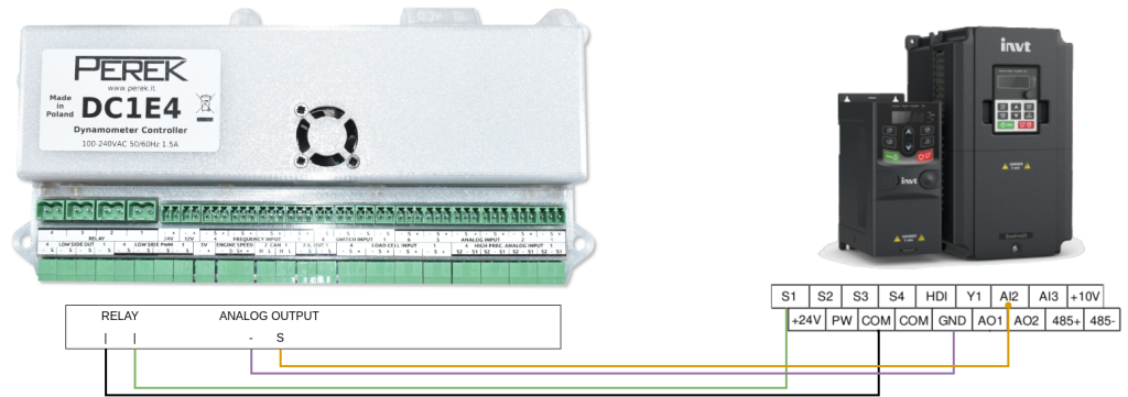
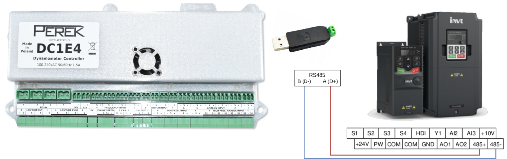
These are the two ways to control the VFD from PEREK dyno controller. One way is to use a relay and digital input to enable the inverter and analog signal to set the desired motor frequency. The other way is to send commands via RS485 interface. RS485 has more advantages over the previous method. Firstly, multiple VFDs can be connected only with a two-wire bus. Secondly, the commanded frequency is precise without any analog offsets on the signal. The third advantage is that INVT RS485 connection offers much more functionality, like setting up most of the VFD parameters or reading diagnostic values like the mains voltage. All the parameters transferred on the RS485 will be logged with the run data.
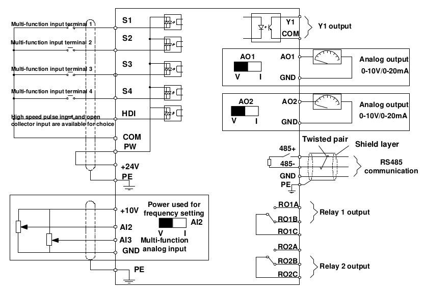
Electrical connection
The VFD can be connected via 4 wires to communicate desired frequency and enable drive.
The other, preferred way is to use a two-wire RS485 connection.
VFD configuration
| Function code | Name | Description | Comments |
|---|---|---|---|
| P00.01 | Channel of running commands | 0: Keypad (“LOCAL/REMOT” light off) 1: Terminal (“LOCAL/REMOT” flickering) 2: Communication (“LOCAL/REMOT” on) | For “4-wire” communication set 1 For RS485 communication set 2 |
| P00.06 | A frequency command section | 0: Keypad data setting 1: Analog AI1 setting (corresponding keypad potentiometer) 2: Analog AI2 setting (corresponding terminal AI2) 3: Analog AI3 setting (corresponding terminal AI3) 8: Modbus communication setting | For “4-wire” communication set 2 For RS485 communication set 8 |
| P00.11 | ACC time | Acceleration time | This value can be reduced from default to allow faster acceleration |
| P00.12 | DEC time | Deceleration time | This value can be reduced from default to allow faster deceleration |
| P02.01 – P02.05 | Motor parameters | Fill all parameters using the motor nameplate | |
| P05.01 | S1 terminal function selection | 0: No function 1: Forward running 2: Reverse running | For “4-wire” communication set 1 |
| P05.37 | Lower limit of AI2 | Voltage on the AI2 input corresponding to 0% frequency | For “4-wire” communication, calibrate to compensate analog signal voltage drops |
| P05.39 | Upper limit of AI2 | Voltage on the AI2 input corresponding to 100% frequency | |
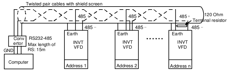
| P14.00 | Local communication address | Setting range: 1–247 When the master writes the slave communication address to 0 indicating a broadcast address in a frame, all the slaves on the Modbus bus receive the frame but do not respond to it. | Local communication address is unique in the communication network, which is the basis for point-to-point communication between the upper computer and the VFD. |
| P14.01 | Communication baud rate | 0: 1200BPS 1: 2400BPS 2: 4800BPS 3: 9600BPS 4: 19200BPS 5: 38400BPS 6: 57600BPS | The baud rate set on the VFD must be consistent with that on the upper computer. Otherwise, the communication fails. A greater baud rate indicates faster communication. |
| P14.02 | Data bit check | 0: No check (N, 8, 1) for RTU 1: Even check (E, 8, 1) for RTU 2: Odd check (O, 8, 1) for RTU 3: No check (N, 8, 2) for RTU 4: Even check (E, 8, 2) for RTU 5: Odd check (O, 8, 2) for RTU 6: No check (N, 7, 1) for ASCII 7: Even check (E, 7, 1) for ASCII 8: Odd check (O, 7, 1) for ASCII 9: No check (N, 7, 2) for ASCII 10: Even check (E, 7, 2) for ASCII 11: Odd check (O, 7, 2) for ASCII 12: No check (N, 8, 1) for ASCII 13: Even check (E, 8, 1) for ASCII 14: Odd check (O, 8, 1) for ASCII 15: No check (N, 8, 2) for ASCII 16: Even check (E, 8, 2) for ASCII 17: Odd check (O, 8, 2) for ASCII | The data format set on the VFD must be consistent with that on the upper computer. Otherwise, the communication fails. Currently, the RTU formats are supported. |
| Baud rate | Max. transmission distance |
|---|---|
| 2400 BPS | 1800m |
| 4800 BPS | 1200m |
| 9600 BPS | 800m |
| 19200 BPS | 600m |
| Modbus address | Data meaning | R/W |
|---|---|---|
| 2000H | 0001H: Forward running 0002H: Reverse running 0003H: Forward jogging 0004H: Reverse jogging 0005H: Stop 0006H: Coast to stop 0007H: Fault reset 0008H: Jogging to stop | R/W |
| 2001H | Communication setting frequency (0–Fmax (unit: 0.01Hz)) | R/W |
| 2102H | Fault code of the VFD | R |
| 3002H | Bus voltage 0.0-2000.0V | R |
| 3003H | Output voltage 0.0–1200.0V | R |
| 3004H | Output current 0.0-3000.0A | R |
The tables above represent only a part of the settings and commands that are relevant to typical needs. The whole INVT manual can be found here:
More information on Modbus protocol:
Dyno2 configuration
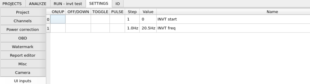
Dyno2 Dynamometer Software – user interface input channels

Dyno2 Dynamometer Software – custom functions
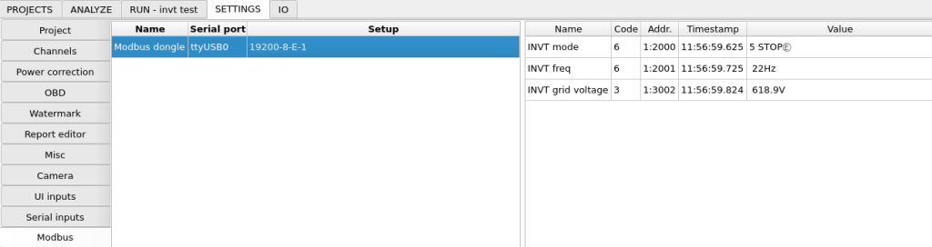
Dyno2 Dynamometer Software – Modbus
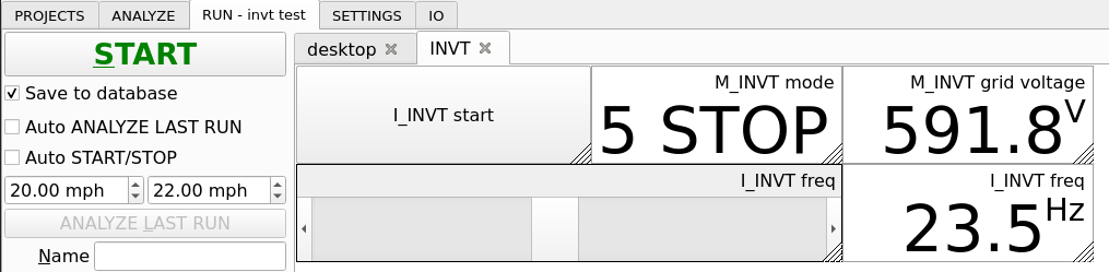
Dyno2 Dynamometer Software – working in run tab
Fan control strategy ideas
- Simple manual control – the fan speed is set manually by you. It can be from a widget in RUN tab, from a potentiometer connected to an analog input on dyno controller, etc.
- Road speed based control – the fan speed is a function of dyno speed. This can be used to simulate road conditions.
- Power based control – the fan speed is a function of power received by the dyno. The vehicle is automatically cooled under load.
- Intake air based control – the fan speed is a function of intake air temperature. This will prevent the intake manifold from heat soaking when idling before run.
- Combined control – for example, the final fan speed is maximum from idea 1, 2, 3 and 4. This is a simple and effective way to provide adequate cooling for the vehicle during power runs with the convenience of manually overriding minimal fan speed.
- Coolant temperature PID control (sensor attached to radiator) – in this method, it’s best to place an additional temperature sensor just after the radiator and use it as feedback for PID. Setpoint should be set manually in the user interface to suit the vehicle you’re currently working on. This method provides perfect control of engine temperature for maximum repeatability between runs.
- Coolant temperature PID control (OBD or CAN) – simplified way to control engine temperature is to use OBD or CAN bus information about engine temperature. With this method, you don’t need to attach the extra sensor, but the engine thermostat can mess up with PID control. Also, the control loop delay is quite long, which makes PID tuning quite time-consuming.
Here are some videos from idea 7 tests: