Brake power supply is intended for use with mains supplied eddy current brake. It is used for the following tasks:
- Rectification of mains AC voltage to DC voltage for brake supply
- Brake force modulation according to logic level, Pulse Width Modulation input signal
BD series brake power supplies comparison
Safety precautions
- The device should be fixed on a hard, flat surface in a well-ventilated area.
- The device must not be exposed to vibration.
- The device air flow must not be obstructed.
- No foreign objects should be inserted into the device.
- Life-threatening, high voltages are present in the device. Make sure that it is disconnected from mains power supply before doing maintenance work. Do not open the device.
- When operating under load, the device radiator will get hot. Before servicing the device wait until it cools down.
- The device is intended for installation by qualified personnel.
- The device must be installed in a closable electrical cabinet and protected from access by unskilled personnel.
- The device should be protected from moisture. It mustn’t be used when wet.
- The device should be protected from ingress of conductive contaminants. It shouldn’t be operated where metal grinding or cutting dust is present in the air.
- The device mustn’t be powered without the enclosure assembled.
- Device installation doesn’t require enclosure disassembly.
- If the device is not working correctly, makes disturbing noises, emits burning smell, it should be immediately powered down. Please contact the manufacturer for repair.
- All dyno metal elements must be connected to safety ground. Any short circuit of live wire to dyno chassis must result in circuit breaker opening. Use of RCD breaker is advised for additional safety.
- Device power supply must be protected with over current circuit breaker with C characteristic. The breaker value should be selected to a minimum that is sufficient to supply the brake.
- The mains power connection must contain a switch that will provide a way to disconnect the device from the grid.
| device variant | one phase supply | three phase supply |
|---|---|---|
| BD2 | 32A | 25A |
Specification
| Supply | 1 or 3 phase L-N 100-240VAC L-L 100-415VAC 50/60Hz |
| Electrical connections | Supply and capacitor: up to 4mm² (10 AWG) Brake output: up to 16mm² (6 AWG) |
| Current rating | 30A continuous @ 40°C ambient temperature 45A momentary |
| Brake discharge method | Freewheeling diode |
| Maximum PWM modulation frequency | 2500Hz |
| Dimensions | 14cm x 12cm x 12cm |
| Operating ambient temperature | −20°C ÷ 50°C |
| Operating humidity | 0% ÷ 95% without condensation |
| Elevation | Up to 2000 m.a.s.l. |
| Mass | 1.1kg |
Grid current use
The current that is required from grid depends on many factors, such as the absorber DC current, absorber resistance and grid supply voltage. Here are some typical cases:
1 phase 230VAC supply, 192V absorber
The required current will be equal or a bit more than the absorber current. If the absorber current is above typical 16A circuit breaker, that may cause it to trip if the load is high for long period. For example if the eddy brake current is 22A, then a 16A circuit breaker may trip after 200 seconds.
3 phase 400VAC supply, 192V absorber
Due to use of 3 phases and higher voltage available at the supply side, the current per phase will be lower than the absorber DC current. Usually peak current per phase will be around 1/3 to 1/2 of the absorber current. This allows for care free use of absorbers that require more than 16A of current.
1 phase 230VAC supply, 96V absorber
The average grid current will be lower than the absorber current, because due to voltage difference, BD2 will be switching the power to the absorber only part of the time. In the end the same absorber wired for 96V will use a bit more current than the one wired for 192V, but the 96V will heat up the BD2 more.
BD2 similarly to other devices that rectify current like for example VFDs, draw current not only at the base mains frequency, but also at harmonic frequencies. This creates apparent power use higher than the active power. Reduction of harmonic current and apparent power can be achieved with use line reactor at the BD2 power supply input. The reactor should be placed before line filter.
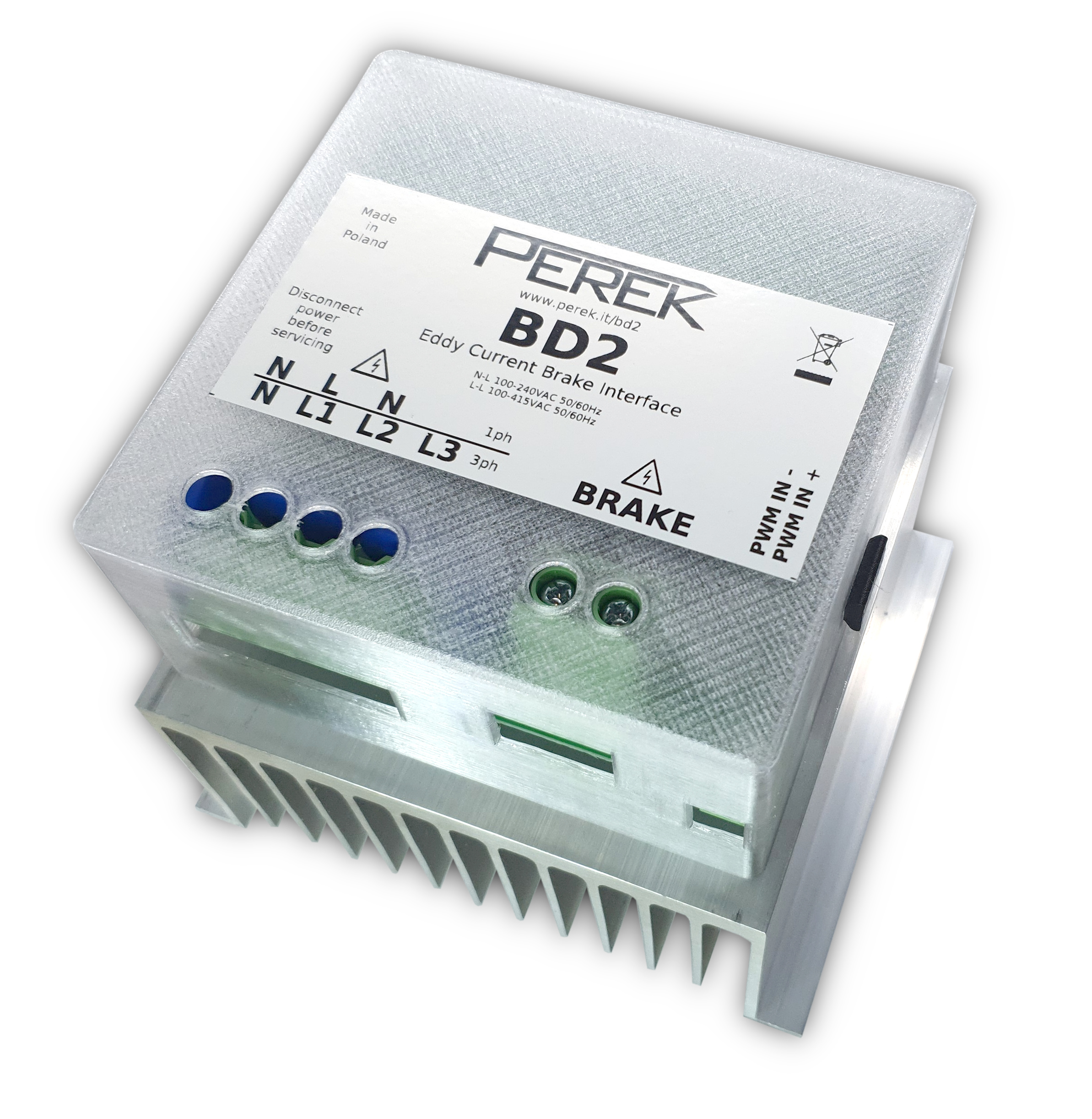
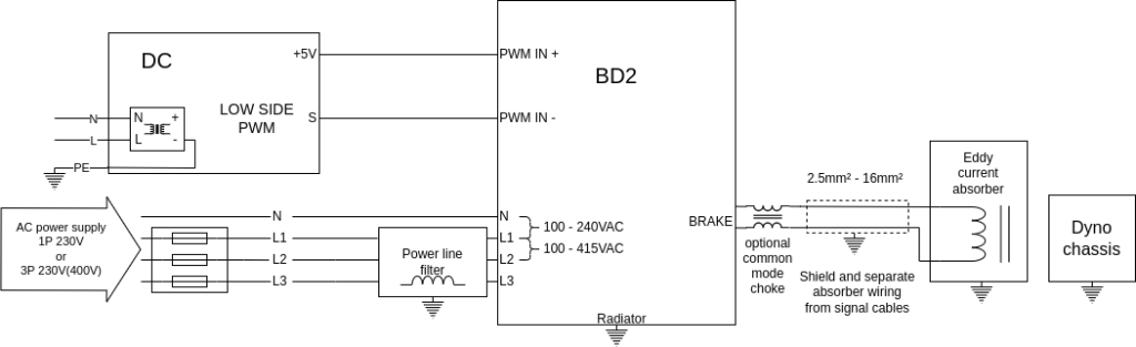
Device connection
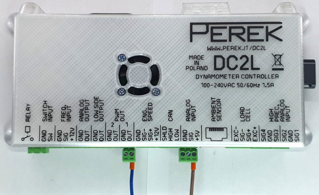
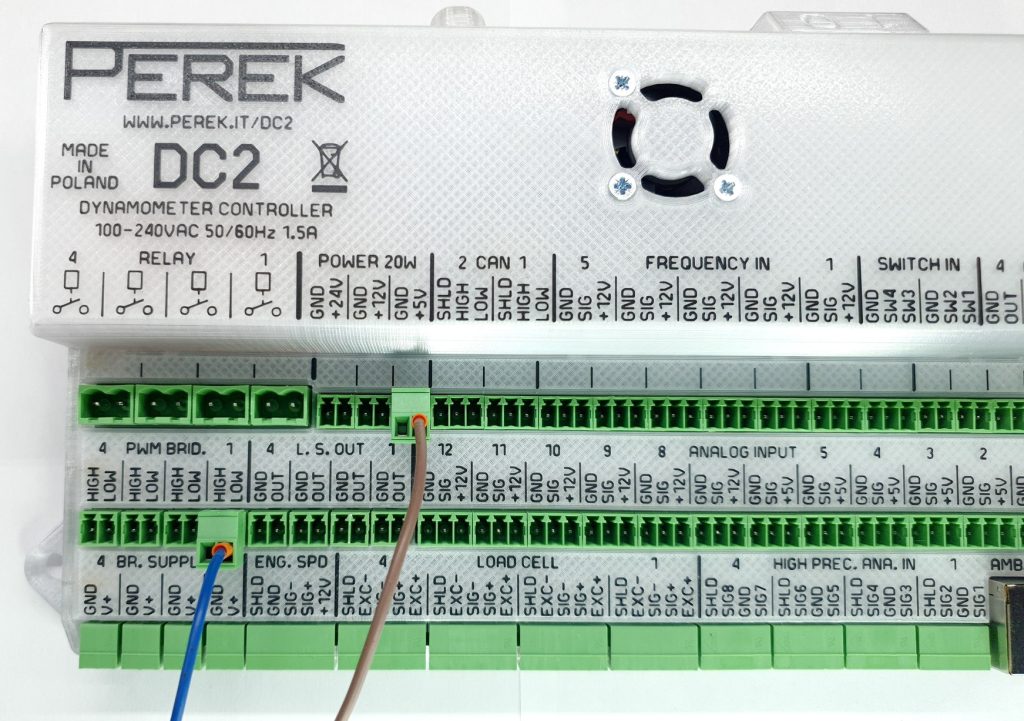
| Terminal | Description |
|---|---|
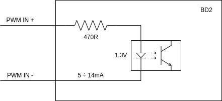
| PWM IN- | PWM input negative |
| PWM IN+ | PWM input positive |
| N / N | Mains supply neutral |
| L1 / L | Mains supply phase |
| L2 / N | Neutral for 1 phase connection 2nd phase for 3 phase connection |
| L3 | Mains supply phase |
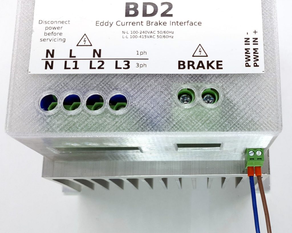
| BRAKE | Eddy current brake connector |
| Terminal | 1 phase connection | 1 phase alternative | 3 phase connection | 3 phase connection low L-L |
|---|---|---|---|---|
| N / N – REQUIRED | N – Neutral | L – Phase | N – Neutral | L2 – Phase 2 |
| L1 / L – REQUIRED | L – Phase | N – Neutral | L1 – Phase 1 | L1 – Phase 1 |
| L2 / N – REQUIRED | N – Neutral | L – Phase | L2 – Phase 2 | L2 – Phase 2 |
| L3 – OPTIONAL | L3 – Phase 3 | L3 – Phase 3 | ||
| Notes: | N-L: 100 – 240VAC All three terminals must be connected | N-L: 100 – 240VAC All three terminals must be connected | N-L1: 100 – 240VAC L-L: 100 – 415VAC | L-L: 100 – 240VAC |
Note: In case of some 1 phase AC mains plugs, the plug can be reversed in the socket and swap N with L. It’s not a problem. The main concern while connecting mains supply to the BD2 is not to make a connection that will create voltage higher than 240VAC between N/N and L1/L terminals.
WARNING! Voltages in the device are life-threatening.
All connections should be made with the device disconnected from main supply.
Connecting the supply is allowed only when the device is safely installed, and its enclosure is assembled.
PWM input circuit is isolated from dangerous voltages, and is the only circuit safe to touch when the device is powered on.
Brake wiring should be routed away from sensitive circuits (i.e. load cell cable). If separate routing is not possible, shielded wiring should be used.
The typical required cross-section of power cables for operation in 40°C is:
- 2.5mm² up to 17A
- 4mm² up to 23A
- 6mm² up to 30A
- 10mm² up to 40A
- 16mm² up to 50A
When installing BD2 with an old, used absorber, check the wiring condition first with insulation tester set to minimum 1500V. Running BD2 with an absorber that has faulty insulation will lead to BD2 device damage.
Current range
BD2 converts the logic PWM signal coming into the input into the high power PWM pulse. There is no automatic current or voltage control implemented. Care must be taken to limit the maximum PWM duty cycle to avoid exceeding the effective current and voltage specified by the eddy brake manufacturer. Over-driving your absorber coils with current higher than nominal for some time can lead to coils damage!
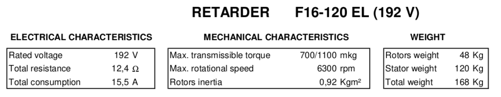
Retarder electrical characteristic is connected with following equation:
- rated voltage = coils circuit resistance * current rating
If one of the parameters is missing in the specification, it can be calculated from the other two.
Absorber nominal voltage rating
| Supply voltage on L-L terminals | Desired absorber nominal voltage |
|---|---|
| 230VAC or 400VAC | 192V |
| 120VAC | 96V |
If you have an absorber with lower than desired nominal voltage, it would be the best to rewire it for higher voltage. Absorbers are usually made with 16 coils rated to 12V. Rewiring the absorber for higher voltage will require to connect all these coils in series (16*12V = 192V).
If absorber rewiring is not possible and current control is not satisfactory, BD2 power supply voltage can be lowered with use of transformer.
When powering eddy brakes from 3 phase supply, take special care to limit the maximum duty cycle to avoid going over the eddy brake specification.
| Supply voltage on L-L terminals | BD2 minimum load resistance |
|---|---|
| 400VAC | 6.8 Ohm |
| 230VAC | 3.9 Ohm |
| 120VAC | 2.0 Ohm |
Avoiding EMI problems
The BD2 functions similarly to VFDs (Variable Frequency Drives) for electric motors. It uses high speed IGBT with high switching frequency to keep eddy current absorber winding current at desired level. During the IGBT turn on and turn off, fast voltage change occurs, which is called high dV/dt rate. This high switching frequency can lead to EMI (Electro-Magnetic Interference) problems in the dyno test cell. These issues can manifest, i.e. as the dyno TV screen malfunctioning.
There are four paths of EMI transfer from the interference source to the interference victim:
- Conductive – through shared electric connection like power supply or signal cable
- Capacitive – through capacitance – large metallic area of source next to large metallic area of victim – this can be just cables laying next to each other – this path conducts interference from high dV/dt voltage change rates present at the brake cable and coils
- Inductive – through common inductance of source and victim – this can also be just source and victim cables laying next to each other
- Radiative – radiated and received through air by source and victim elements acting like antennas.
How to avoid EMI interference? Here are some low-cost guidelines you must adhere to, when designing the dyno components layout.
- Ensure that all metallic dyno elements are properly grounded – connected to building safety ground. The connections must be made with thick cables and have good conduction to the grounded elements. Here is a basic grounding checklist:
- Dyno frame
- Eddy current brake frame
- BD2 radiator
- DC controller safety ground pin in power connector
- Interference victim – monitor ground pin in power connector
- Cable shields
- Separate interference source cables from victim cables – power cables from signal cables. No signal cable should run near the BD2 – brake cable. You should also avoid running signal cables near power supply cables to the BD2.
- The high voltage capacitor must have as short connection as possible to the BD2. Short distance from BD2 to the brake will also reduce the possibility of interference.
- Use twisted pair cables, where required, i.e. CAN bus cable.
How to deal with EMI interference that is still present? If previous guidelines were not enough or were hard to implement, there are still some ways to save the day:
- Use cable shielding. The cable shield must be well grounded. In case of power cables, the shield can be grounded on both cable ends. The cable shielding helps to block dV/dt interference from travelling through capacitance between cables. You can shield interference source cables like BD2 – brake cable and capacitor cable. You can shield victim cables that receive the interference. You can shield both.
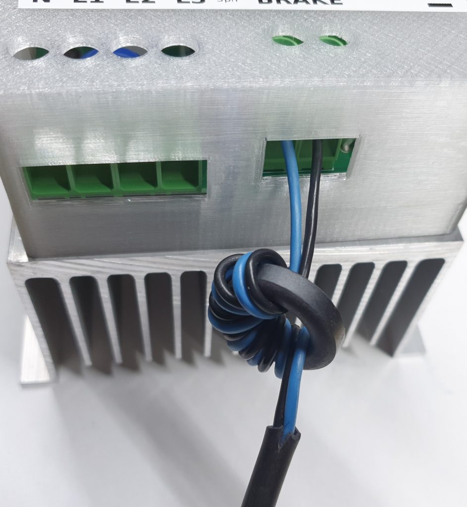
- Install common mode choke on BD2 – brake cable. These will block high frequency common-mode current path.
- Install ferrite rings / chokes on BD2 power supply cable.
- Install ferrite rings / chokes on victim cables. For example: HDMI cable.
- Install line filter on BD2 power supply cable. It will block conducted interference going to other devices through the building power supply.
- Install BD2 in a closed metal cabinet.
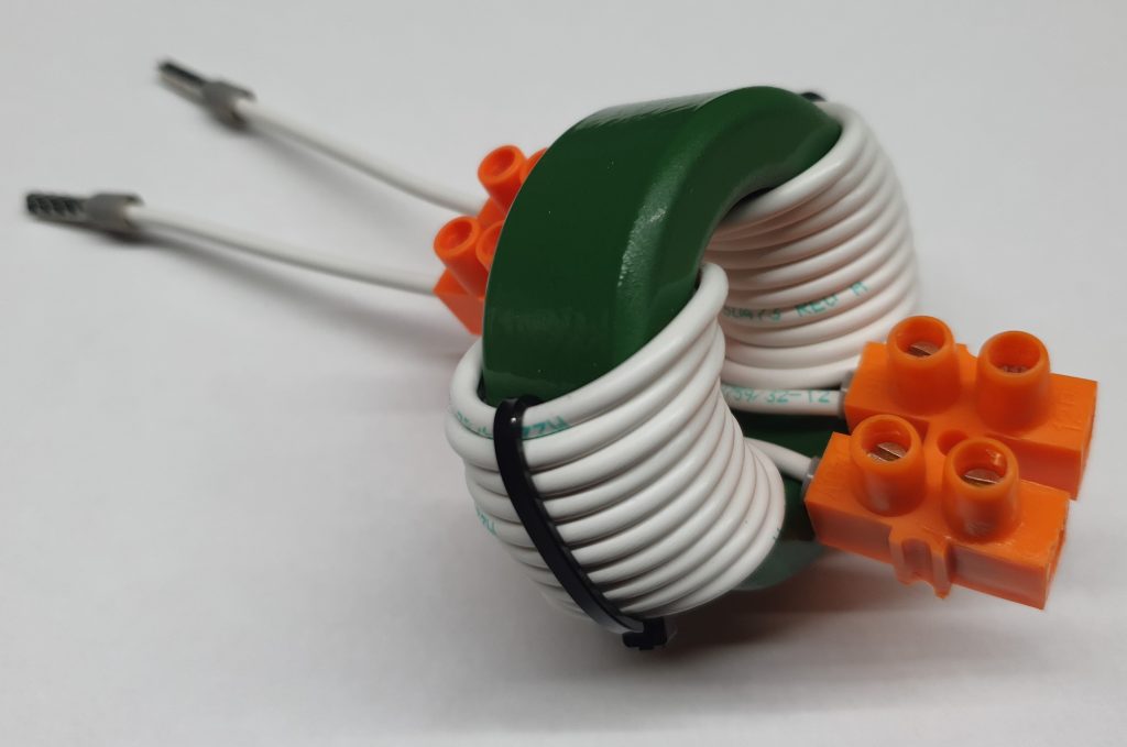
BD2 – absorber ferrite core cable choke
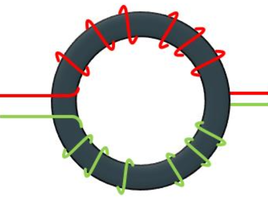
If BD2 to eddy current absorber cable is longer than 1.5m it’s advised to install a common mode choke on the cable. The choke can be easily made from a ferrite ring and some wire. Effective choke should have at least 0.5mH inductance. The equation for ferrite ring choke inductance is:
L = T² * AL
L – inductance
T – turns (winding) count
AL – ferrite core coefficient
Let’s go through example calculation. We can take a ferrite ring with dimensions 48mm x 30mm x 15mm with AL = 3200nH. Required inductance = 0.5mH = 500000nH
The required winding count T = sqrt(L/AL) = sqrt(500000nH / 3200nH) = 12.5
We divide the winding count by 2 and round up to give us 7 windings on each wire. Both wires must have same winding count. Take care to wind the wire in the correct direction. The wires from the BD2 should both come out from one side of the ring and the wires to the eddy brake, from the other side.
Warranty
The producer guarantees that the device is manufactured according to accepted craftsmanship practices, and it meets the applicable standards. Correct device operation is guaranteed for 24-month period starting from date of purchase.
The guarantee does not cover damages caused by improper installation, usage or noncompliance with instruction manual.
The device is intended for installation by qualified personnel. Device final performance and suitability for a particular application is dependent on the user, and thus it is not guaranteed by the manufacturer.
These specifications are subject to change without notice.