Dyno2 software implements flexible control loop system, that allows user to implement optimal control architecture for their dynamometer. PID controllers are the basic building blocks of the system. Each of the controllers is responsible for keeping the desired value of dyno parameters such as engine speed, absorber torque, actuator position or any other parameter available in software. Every controller output is normalized to 0.0 ÷ 1.0 range to implement the integrator windup limit, when the output is saturated.
There are three basic controllers running in the microcontroller with 1000Hz update speed:
Analog Input Controller
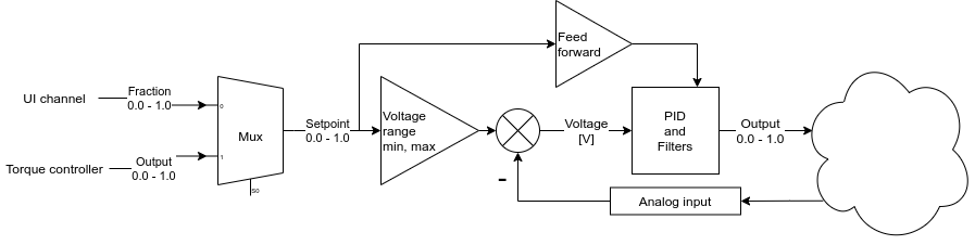
This controller is used to keep constant signal on controller analog input. It can be used to control the position of water brake valve, or engine throttle body. Any object that gives position feedback with analog signal is suitable.
The controller Setpoint can be sourced from the user interface or from the Torque Controller.
Torque Controller
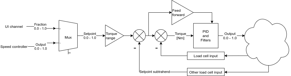
Dynamometer absorbers usually have non-linear characteristic in relation to control signal. The role of the Torque Controller is to keep the desired absorber torque, regardless of its temperature or shaft rotational speed, by using load cell signal feedback. It eases work of the Speed Controller and also allows running the software in constant absorber torque mode. Another useful feature of Torque Controller is splitting of torque demand between available dynamometer absorbers.
If “Send BD3 control message” is checked in CAN interface settings, the torque controller output is automatically sent to the corresponding BD3.
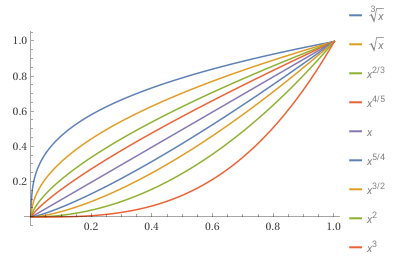
The torque controller can apply a function to it’s output to linearize absorber torque output in reaction to calculated PID controller output. For example:
-Eddy current absorber require a bit more current for same torque change in lower range than in higher. We can achieve better control in whole range by applying x^2/3 function to PID output.
-Water brake ball valve flow change may be higher in lower range of opening angles, then the flow change is small in relation to angle. We may apply x² or x³ function to output to improve the control.
Speed Controller
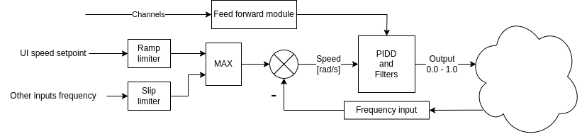
The most important controller is the Speed Controller. It is used to keep the engine rotational speed constant. It uses frequency input signal as feedback. Its output can be fed to Torque Controller or directly to device PWM or analog output. The Speed Controller has build in Ramp Limiter and Slip Limiter that are used to limit mechanical load on a car and dynamometer hardware.
Ramp Limiter is used to limit slow down rate of speed setpoint. This reduces load on vehicle axles.
Slip Limiter is responsible for speed synchronization between dyno rollers. If one roller set has lower inertia or the stronger absorber, the Slip Limiter “tells” it to wait for the slower braking roller and to keep the speed constant across the rollers.
Acceleration Controller
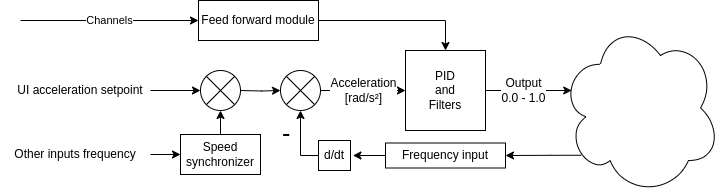
If you are interested in keeping acceleration constant, an Acceleration Controller will come in handy. Unlike speed ramp, it operates directly on acceleration, and it is optimized to keep it at the desired value.
Acceleration Controller is equipped with Speed synchronizer. It modifies desired acceleration rate per controller to keep speed constant across wheels and average acceleration at desired value.
Functions PID
Another type of controller that is available in the system is the Functions PID. It runs in the client software with 100Hz update rate, and it is suitable for controlling parameters that don’t change so fast to require real time 1000Hz update rate. The advantage of this controller is that it can use any dyno data channel for setpoint and process value.
Example control architectures
Basic control architecture
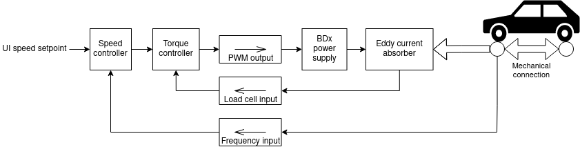
The above basic control architecture is suitable for typical dynamometers.
- The desired speed is set with the software user interface, converted to signal frequency and fed as setpoint to the Speed Controller. Speed Controller compares the setpoint with the frequency signal from dyno and, with use of PID, creates 0.0÷1.0 control signal.
- The control signal from Speed Controller goes into Torque Controller and is multiplied by torque range to get torque setpoint. The Torque Controller compares the setpoint with the load cell signal and, with use of PID, creates a 0.0÷1.0 control signal.
- Output from the Torque Controller is routed to PWM output and to eddy current brake interface to create desired torque.
To implement above system:
- Connect roller speed signal to Frequency Input 1
- Connect load cell signal to Load Cell Input 1
- Calibrate load cell
- Connect BD1 control input to DC1 PWM output 1
- Set SETTINGS/Dyno/PWM low side output/Source: torque controller 1 output
- Set SETTINGS/Dyno/Torque control/Setpoint range: [torque range of your absorber]
- Tune Torque PID coefficients
- Set SETTINGS/Dyno/Torque control/Setpoint source: speed controller 1 output
- Tune Speed PID coefficients
Dual Torque Controller architecture
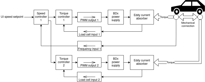
The basic architecture can be extended with a second absorber and a control loop for it. The desired torque range that will be requested from each brake can be set with Torque Range setting in Torque Controller.
Dual Speed Controller architecture
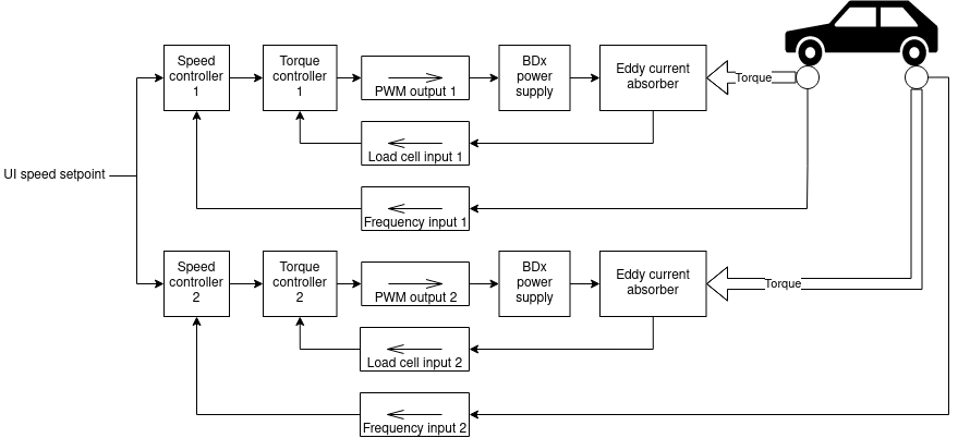
Dual Torque Controller architecture can be further updated with second speed sensor and second Speed Controller. With this architecture, mechanical connection in 4×4 chassis dynamometer is not required for vehicles that don’t have traction control system. Each Speed Controller is responsible for keeping the rotating roller at the speed set in the user interface.
Dual Brake system
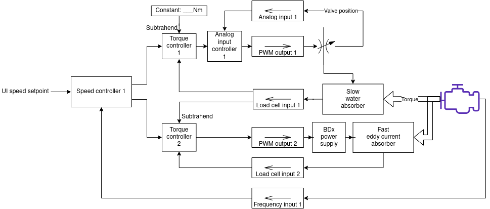
Water absorber can absorb a lot of power for a long time, however it has slow response to engine torque output. Eddy current absorber has the fastest response, however it’s not suitable for long runs, as it heats up relatively quickly.
With the DC1 controller and Dyno2 software, we can set a system that uses both absorbers in one dynamometer. Water absorber is used to absorb lots of energy during long stress test and eddy current absorber provides snap response in transient situations.