The software supports reading diagnostic data through vehicle OBD / UDS interface. It is possible to use wired USB interface or wireless Bluetooth interface. OBD / UDS system configuration is done in SETTINGS / OBD / UDS.
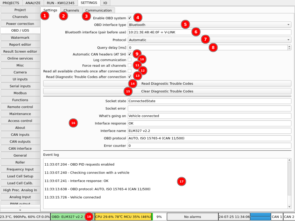
OBD Configuration:
- Tab with interface setting
- Tab with channels configuration
- Communication log for troubleshooting
- Main OBD system switch to easily enable and disable the system when not in use or if it needs to be reset
- Interface type selection. Available options are:
- Bluetooth
- USB / Serial – for basic interfaces that use typical serial communication
- USB / FT2xx – for interfaces using FTDI chip for USB communication
- Device selection. It will be different for different interface types. Right click to select available interface.
- OBD protocol selection. Typically, it should be automatic. Can be set to a specific protocol for faster connection or if correct protocol is not detected automatically.
- On some fast OBD interfaces, queries and replies from multiple ECUs can get mixed up. Adding a delay between queries can fix it.
- Enables automatic ECU header detection and physical addressing. It’s another method to fix up queries and replies mix up on fast interfaces.
- Switch to enable logging whole communication with OBD interfaces. Use it in case of trouble with connection to vehicle. Keep disabled during normal use to avoid wasting resources.
- Forces simple one by one reading of all configured channels and ignoring priorities and availability.
- Forces a single read of all the channels that the vehicle reports as available after connection. Can be used to get initial values on the channels and to verify if they are really available.
- Enable reading of Diagnostic Trouble Codes after connection. DTCs can reduce engine power or availability of the channels. It’s good to always start with no DTCs active.
- Manually read DTCs.
- Clear DTCs
- Current information about OBD connection and interface
- Event log for basic troubleshooting
- Statusbar button that shows current OBD information in short. Clicking on this button enables or disables the OBD system. Same effect as clicking on (4) checkbox.
Channels can be configured in Channels tab. The channel list is editable. You can add your own channels and remove the existing ones.
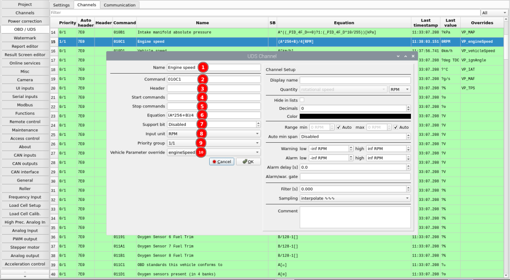
- Channel name
- Main command to send to the vehicle
- Custom header if required
- Commands to send before the main command
- Commands to send after the main command
- Equation to calculate the channel value
- Support bit position for PIDs that contain multiple channels
- Input unit of the value calculated from the equation
- Readout priority
- Option to override a built-in Vehicle Parameter channel with the value of this channel
First thing you want to do after running the software is to import the standard channels list. You can do it by right-clicking the channels list and selecting “Import from website”. In the dialog, select “OBD2 service 01 standard PIDs” and click OK.
Then you need to assign priority to the channels you would like to read from the vehicle. Right-click on a channel and select the priority from the menu. The priorities have the following meaning:
0/1 – the channel will not be updated
1/1 – the channel will be updated as often as possible (the channels from other groups will still be updated)
1/2 – the channel will be updated every two updates
…
1/100 – the channel will be updated once every 100 updates.
…
1/1000 – the channel will be updated once every 1000 updates.
You should assign 1/1 priority to the channels that have fast changing information, like the “Timing advance”. You can assign 1/100 priority to the channels that doesn’t need frequent update, like the “Engine coolant temperature” channel.
Of course, the update rate is still limited and if there are 200 channels assigned to the 1/100 group, every one of this channel can be updated once every 200 reads.
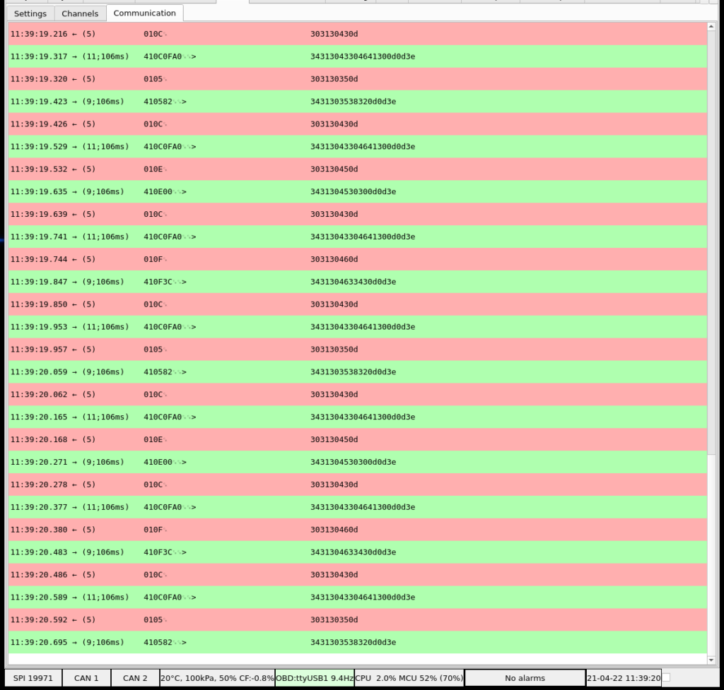
The whole communication with OBD interface can be observed in Communication tab if option Log communication is checked.
USB / Serial interface connection procedure
- Select OBD interface type: USB / Serial
- Select USB / Serial interface port with mouse right-click, i.e. ttyUSB0
- Make sure the baudrate is correct for your interface. Typically, 34800.
USB / FT2xx interface connection procedure
- Select OBD interface type: USB / FT2xx
- Select FT2xx interface with mouse right-click. If nothing appears, your interface may not use FT2xx communication, and you should try USB / Serial option.
- Make sure the baudrate is correct for your interface. Typical baudrate is 34800, but some interfaces use higher values. For example, OBD Link EX uses 115200 by default.
Bluetooth interface connection procedure
Connect the interface to a vehicle and turn the ignition ON to supply power to the interface. Interface should be possibly close to the controller. Avoid any obstacles that can interfere with wireless connection.
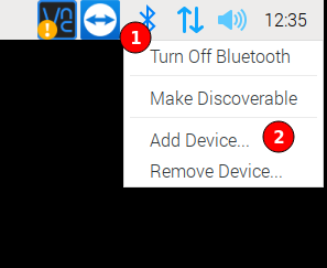
Pairing with system Bluetooth manager
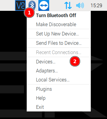
Pair the interface in operating system. Click Bluetooth icon (1) and select Add Device… (2)
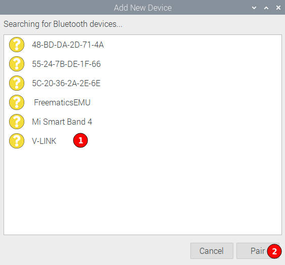
Wait for the interface to show up on the list. If the interface doesn’t show up, it may be too far from the controller, or it may be not powered.
Select the interface (1) and click Pair (2).
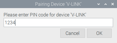
Enter PIN number. Typically 1234 or 0000. Click OK.
The system shows the following message:
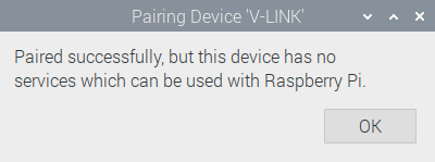
The pairing is correct, just the plain operating system doesn’t know how to use the device. The dyno software knows what to do with it.
Pairing with blueman Bluetooth manager
Pair the interface in operating system. Click Bluetooth icon (1) and select Devices… (2)
In the new window, click Search (1) and wait for your device to show up. Right-click your device (3) and click Pair (3).
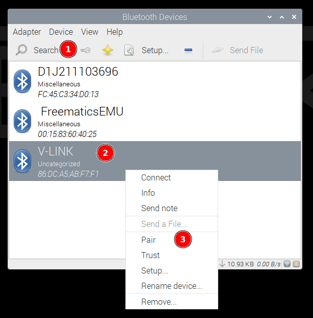
Enter PIN number. Typically 1234 or 0000. Click OK.
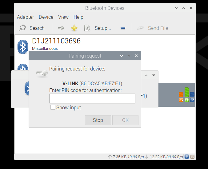
The pairing is finished.
Connecting interface in dyno software
In dyno software, select OBD interface type: Bluetooth
Select Bluetooth interface with right mouse click, i.e. AA:BB:CC:DD:EE:FF = V-LINK
Wait some time for the Bluetooth to complete connection procedure

Using external Bluetooth adapter
If you place your DC1 controller in a closed metal cabinet, the Bluetooth connection quality with the interface placed in the car will be quite poor. You can use external USB Bluetooth dongle on USB extension cable to improve the situation greatly. So far, we tested a dongle based on a “CSR8510 A10” chip, and it worked flawlessly. To use an external Bluetooth adapter, you need to disable the internal one. Edit the /boot/firmware/config.txt file:
sudo nano /boot/firmware/config.txtAdd the following line at the end of the file to disable the built-in module and reset the system:
dtoverlay=disable-bt