RUN tab is used to make new measurement and to work with the car by using dyno brake and speed control.
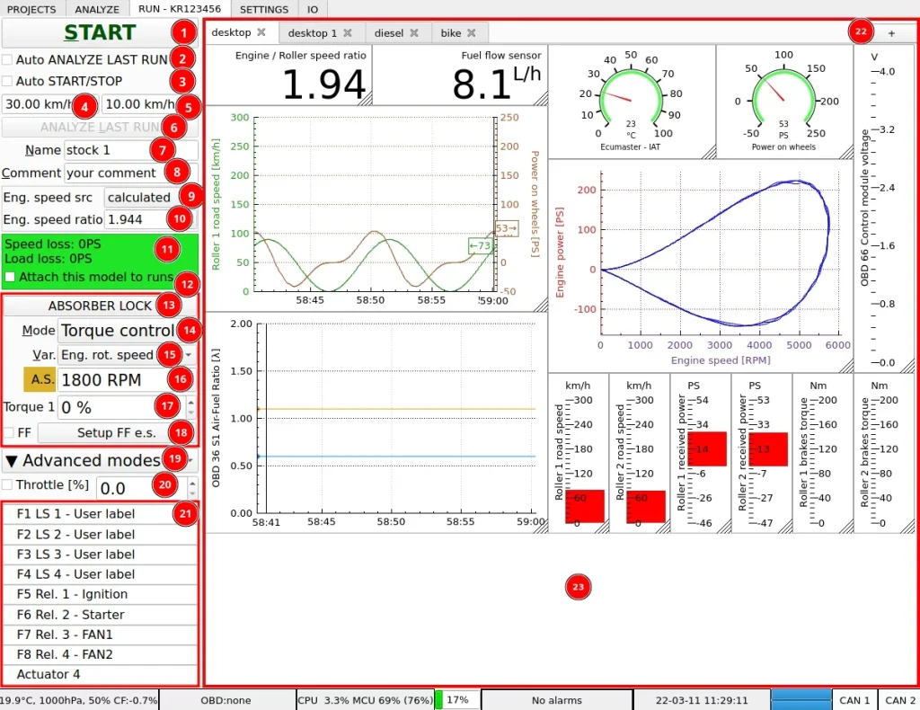
- START / STOP – start or stop saving measurement data
- Auto analyze will load the run to ANALYZE tab after it’s finished.
- Automatic START / STOP enables starting and stopping the run automatically by monitoring the dyno road speed.
- Automatic start speed. When the speed goes above this value, data logging is started.
- Automatic stop speed. When the speed goes below this value, data logging is stopped.
- ANALYZE LAST RUN – shortcut for loading measurement data to ANALYZE tab after finished run
- Current run name. It can be used to label the run like i.e. warm-up, stock, tune. If the project have a run with the same name, a number after the name is added and incremented. i.e. “stock”, “stock 1”, “stock 2”.
- Current run comment. It can be used to describe the run in few more words than the run name.
- Engine speed source selection widget is used to select the source for engine speed used in calculations. Following options are available:
- calculated – the engine speed is calculated with a constant ratio to dyno roller speed. This is the primary, general purpose choice for measurements.
- eng. speed in – the speed is sourced from “Engine speed” input in the controller. You can use this option through the whole run or if the speed signal is glitchy you can switch to this option to get the speed ratio and the switch back to “calculated” mode.
- VP_engineSpeed – this option takes engine speed from VP_engineSpeed channel. This channel in turn can have data from digital source like OBD or CAN bus channel. The channel used for speed should have “Vehicle Parameter override” set to “engineSpeed”.
- OBD – keep in mind that OBD can be relatively slow and may have a low sampling rate with lots of channels enabled. With this option you will get precise engine speed values, but in between samples the values will be interpolated. You may be better off to use it only to get the speed ratio and switch back to “calculated” mode.
- CAN bus – the CAN bus usually has the engine speed transferred at a reliable fixed speed and can be used for whole run without issues.
- Engine speed ratio for calculated engine speed source. The ratio can be automatically calculated by using tools available on right click:
- Set from current engine speed – the ratio is calculated from current speed using entered engine speed.
- Set from max engine speed – the ratio is calculated from maximum recorded speed using entered peak engine speed.
- Get from OBD – the ratio is calculated from OBD interface information.
- Loss model – model used to estimate power lost in the drivetrain and on the tire-roller contact patch. The model is used to calculate engine power from the power measured on dyno rollers. Loss model calculation tool is available by right-clicking on the Loss model label. Once measured and calculated, the model can be attached to new runs to avoid doing coastdown every run.
- Brake controller – widgets responsible for controlling absorption dynamometer absorber.
- Absorber lock – emergency braking with absorber or locking to get in and out of rollers. Right click to select channel for external triggering of this function.
- Brake controller basic modes:
- Brake OFF – dyno absorber is disabled
- Torque control – each brake channel is controlled manually and separately by sliders (18)
- Torque c. joined – all brake channels are controlled manually together by sliders (18)
- Speed control – the software keeps engine speed constant
- Accel. control – the software keeps engine acceleration or deceleration constant
- Brake controller control variable. The control can be based on dyno road speed or on engine rotational speed.
- Anti Stall is used to avoid engine stalling. Absorber is always disabled below this speed.
- Target for current control mode. In this case fraction of available absorber torque in torque control mode.
- Feed Forward setup to help PID control if engine power change is abrupt.
- ADVANCED MODES SELECTOR – run predefined, more advanced dyno modes that run over the brake controller basic modes. The available modes are:
- Road simulation – simulation of load in road conditions and driving cycles for emission tests
- Ramp test – acceleration control with some extra functions like initial speed hold, top speed hold, accelerated coastdown
- Sequence – speed target and throttle sequence
- Inertia calibration – up / down ramp looping to adjust system inertia
- Custom acceleration rate – programmable acceleration curves based on any channel
- Custom torque – programmable torque curves based on any channel
- Sim connector – dyno control based on parameters from racing simulator
- Log player – dyno control based on playback from racing datalogger
- Throttle control – value used to control engine throttle. More information about throttle control can be found on the throttle control page.
- Outputs control – this section of the application shows current controller output state and allows controlling their state. This area also contains the actuators widgets.
- Desktops bar – shows currently opened desktops (workspaces) and allow manipulating them.
- Desktop area – area that can be freely configured by user and is used to visualize information channels available to dyno software.
Using Loss Model in RUN tab
Loss model can be used in RUN tab to calculate the engine power on the run using losses estimation from previous run.
Auto START / STOP
The automatic START / STOP feature, together with the Auto ANALYZE LAST RUN allows you to make runs, and view them in ANALYZE tab without using mouse or keyboard. The start and stop speeds are only used to trigger logging, and you don’t need to adjust them per vehicle to get any specific engine speed range displayed on the graph. The software automatically selects the power pull to display in the logged data. By default, this is the range from peak speed to the first local speed minimum before it. This way you can set auto START / STOP speeds once to your preference, and use the same values for every vehicle.
Top to bottom measurement on a PTO tractor dyno
Multiple runs in a single file
Because the range displayed on the graph in analyze is independent of the logged data range, there are some cool tricks we can use to save time. In a single file, we can do few test runs to check if the engine is warmed up and producing repeatable runs, then in the same file we can have the final run which will be automatically selected for display.
Basic brake controller modes
Brake controller provide some basic brake operation modes that are sufficient for using the dyno for tuning and plotting power curves. The modes available are:
- Brake OFF – in this mode the absorber is disabled, and the dyno runs like an inertial only dyno. It is good to make smooth and repeatable power curves. If the dyno rollers inertia is low and the car is turbocharged, this mode can give lower power results than the modes with absorber, as the turbo won’t have enough time to spool up.
- Torque control – this mode provides control over the torque load of the absorber. This mode is suitable for turbocharged cars and for making smooth, repeatable power curves for a customer.
- Torque control joined – mode similar to one above, but all absorber are controlled together with a single value.
- Speed control – mode used for engine control unit tuning. With this mode, we order the dyno to keep the dyno and engine speed constant. By doing it, the dyno locks the engine speed coordinate of the ECU map. We can move on load coordinate of the ECU map by operating the throttle. This allows precise tuning of the ECU maps.
- Acceleration control – this mode keeps engine acceleration or deceleration at a constant value. This mode is useful to do power sweeps for tuning or making engine characteristics for a customer. In case of chassis dyno, the power curves from this mode can be more “wavy” than the ones from Brake OFF or Torque control modes. It’s a result of the PID controller fighting to get the acceleration at a desired value and the car using its freedom to move on the rollers. The results depend on how tight the car is strapped to the dyno and how aggressively the PID controller is set up. With relaxed PID setup, this is a very good mode for making engine characteristic plots. In case of engine or PTO dynamometer, where coastdown is not required, a good method to make the measurement is to accelerate the engine to top speed and then start the test with negative acceleration value.
Feed forward
The feed forward system is used to provide information about anticipated required controller output to the PID controller. This improves control performance when the engine power is abruptly changed. This happens for example when the turbo spools up quickly.
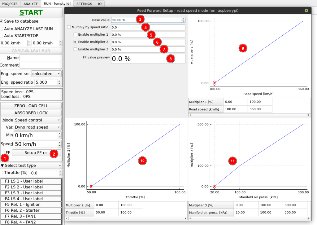
- Checkbox to quickly enable or disable feed forward
- Button to access feed forward setup
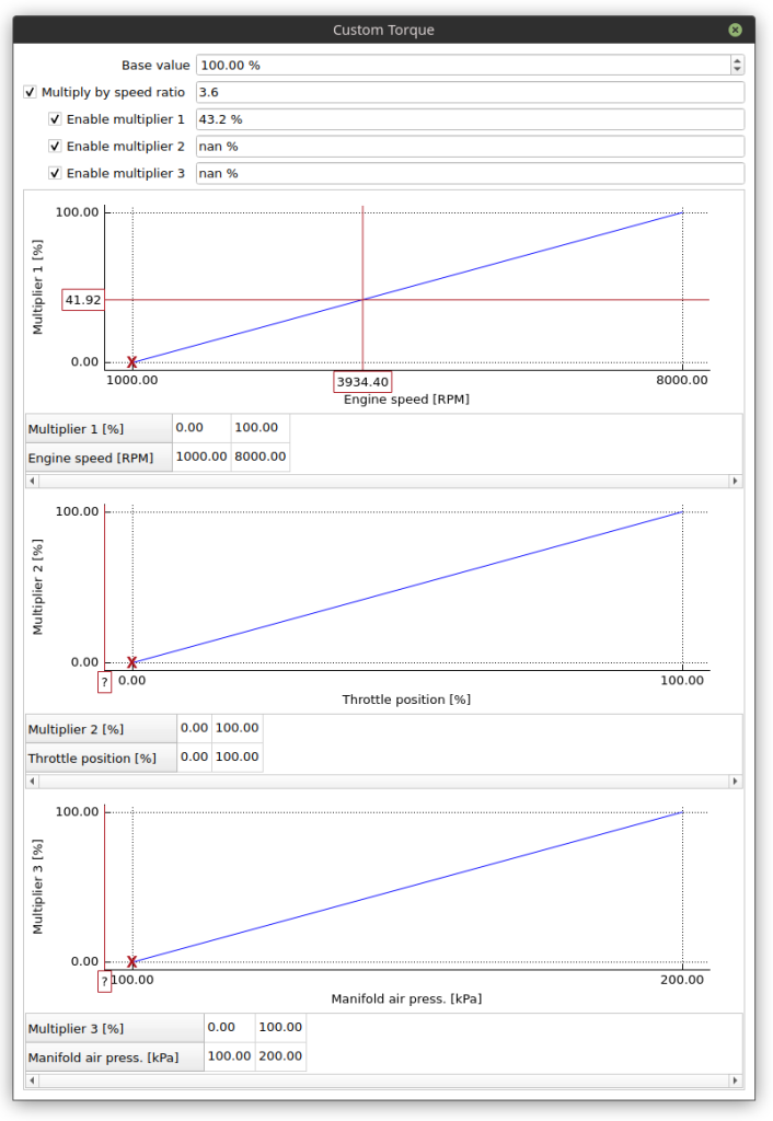
- Base value
- Option to multiply by engine – roller speed value
- Option to enable multiplier 1
- Option to enable multiplier 2
- Option to enable multiplier 3
- Final feed forward value preview
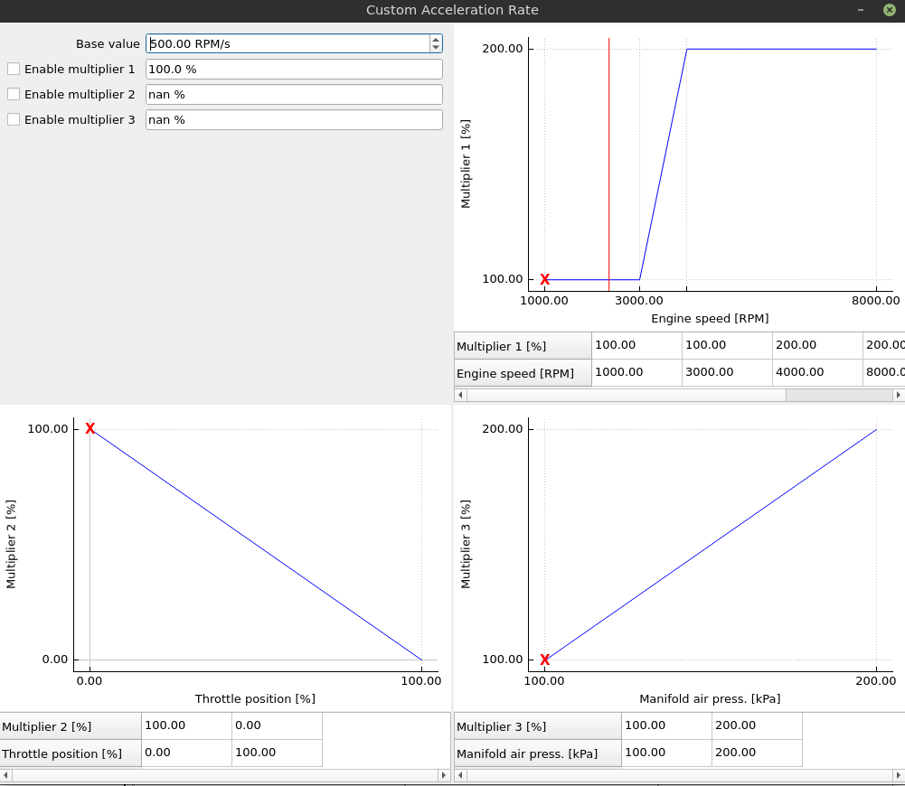
- Multiplier 1 characteristic
- Multiplier 2 characteristic
- Multiplier 3 characteristic
The x-axis on each multiplier characteristic can be freely changed from the right-click menu.
The feed forward system has total four sets of setups. For speed control and acceleration control modes, and then for road speed and engine speed in each mode.
Feed forward is calculated in the following way:
Feed forward = Base value * (optionally speed ratio) * (optionally multiplier 1) * (optionally multiplier 2) * (optionally multiplier 3)
Multiplier values are sourced from characteristics.
The feed forward value is then distributed to particular PID controller channels with feed forward gain in each channel (kFF). By setting the kFF to 1.0, you set full feed forward on this channel. If you want to send 100% of the feed forward to the first controller and 50% to the second one, you can use kFF=1.0 in first one and kFF=0.5 in second one.
Advanced modes
Road simulation
The road simulation advanced test mode uses configured parameters and measured speed and power to control vehicle acceleration on the dyno:
Acceleration target = f(dyno speed, power on wheels, parameters)
This will simulate how the car would behave while driving on the road.
Additionally this mode has a support for driving cycles used in standardized vehicle tests.
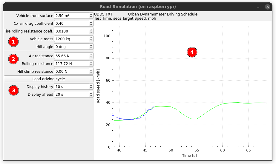
- Parameters of vehicle and road
- Calculated resistance forces that act on the vehicle
- Driving cycle display setup
- View of drive cycle target speed and achieved speed
Ramp test
The ramp test extends basic acceleration mode with some advanced functions.
With simple acceleration mode, the turbo of the turbocharged engine may not have enough time to spool up. As a result, torque and power in lower speed range and sometimes in the whole range are lower than the maximum that the engine can produce when fully loaded. To solve this, the engine is held at a constant preset speed to spool the turbo at the start of the run.
When during standard test procedure the clutch is depressed at the top engine speed, the power transfer from vehicle to dyno instantly drops. Due to use of zero-phase filtering, which is required to correctly filter (smooth) the graphs, the end of the power and torque curves fall down below the real power output of the engine. The significance of this effect depends on how strong the filtering (smoothing) is set up. To solve this, the engine can be held at top speed and high power for some time before pressing the clutch
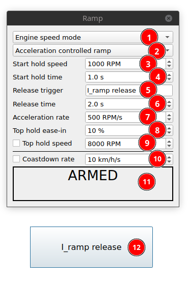
- Test mode: road speed or engine speed
- Ramp mode:
- Speed controlled ramp – this ramp uses constant speed mode of the brake controller by increasing the target speed constantly to achieve desired acceleration. In this mode, the engine or dyno speed will follow the anticipated speed ramp faithfully. This mode can cause loops on engine characteristic plots. If the engine power increases rapidly, and it accelerates above the desired speed, it will be pulled back to this desired speed.
- Acceleration controlled ramp – this ramp uses constant acceleration mode of the brake controller. In this mode, the controller will work to keep the acceleration as desired level. If the engine power increases rapidly, and it accelerates faster than the desired target, the controller will correct the acceleration, but it won’t stop it to get back on the theoretical speed ramp.
- Hold speed – the speed that is held to spool up the turbo
- Hold time – time to spend at hold speed to spool up the turbo
- Release trigger – the channel with “logic” quantity used to end the hold phase earlier
- Release time – transition time from hold to full acceleration
- Acceleration rate
- Top hold ease in – smooths the transition between acceleration and top hold stages
- Top hold speed – if enabled the controller will hold the engine at this speed to avoid hitting rev limiter and rounding off effect of power curve at top speed
- Coastdown rate – if enabled, this option accelerates coastdown. This can speed up measurement on dynos with heavy rollers that use a lot of time for coastdown. Don’t use excessive acceleration rates, as this may cause inaccuracy in coastdown losses measurement.
- Current test state
- ARMED – the test is ready. Accelerate at will.
- HOLDING – the test is holding the Hold speed.
- RELEASING – the test is in transition between HOLDING and ACCELERATION
- ACCELERATION – the test is controlling acceleration at rate entered in Acceleration rate field.
- Example button placed on desktop to trigger manual release from hold state
Tracking threshold setting in SETTINGS / Misc – this value has several uses in the algorithm, and is generally used to inform it, what amount of error between desired speed and actual speed should be accepted.
- During hold state, if (|current speed – hold speed| < tracking threshold), the hold time is counted down to pass to the next state. If the speed difference goes above the tracking threshold, the timer is reset.
- During acceleration state in speed controlled ramp if (current speed > target speed – tracking threshold) the speed target is increased. In other case, the speed target is reduced, so we can start accelerating again.
- In acceleration state, if (current speed < hold speed – tracking threshold) the hold state is activated again
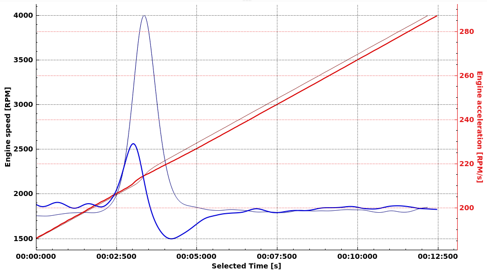
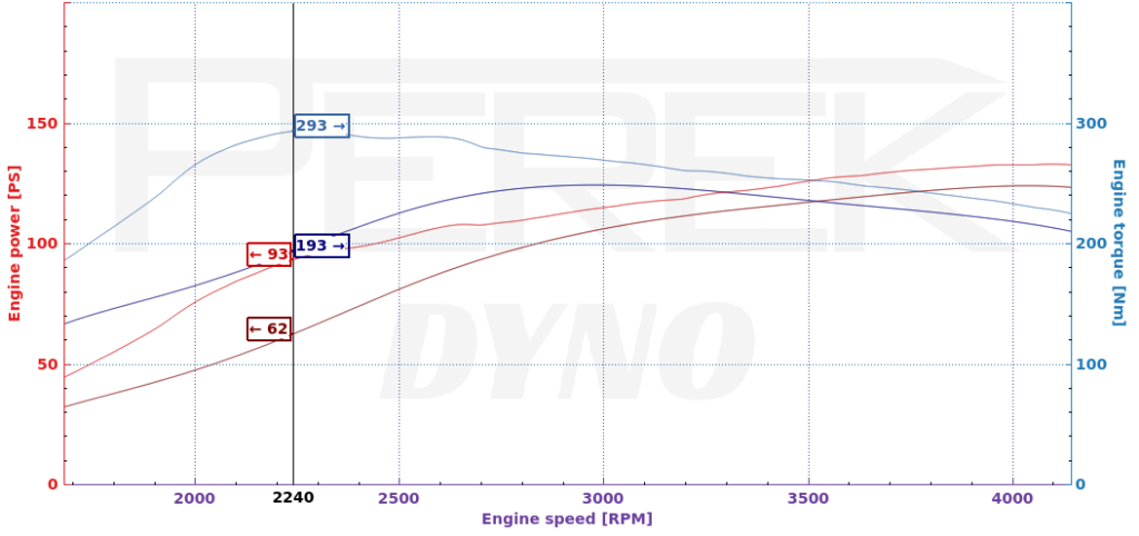
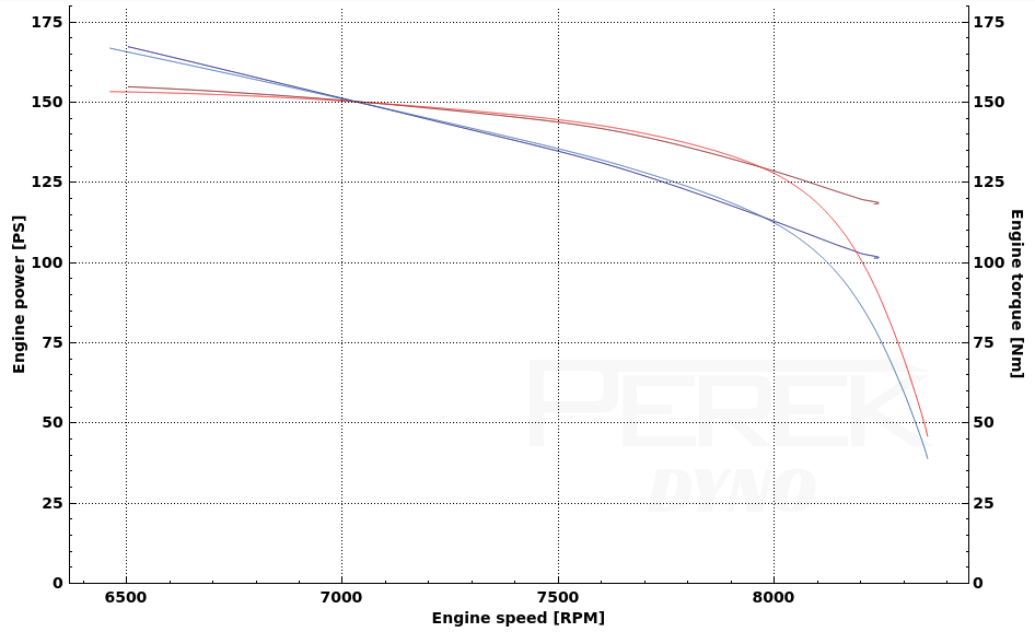
Speed (thick line) vs acceleration (thin line) controlled ramp. Acceleration target: 200RPM/s. Power was increased at 2000RPM.
Speed ramp will reduce acceleration below the acceleration target (even to negative values) to get back to the desired speed slope.
The acceleration ramp will reduce acceleration back to the desired value, but the theoretical run time will be reduced as a result of the abrupt power increase.
Sequence
The dynamometer software enables to program engine test sequences that will control engine speed and throttle opening during the test. Test sequence length and number of points is unlimited.
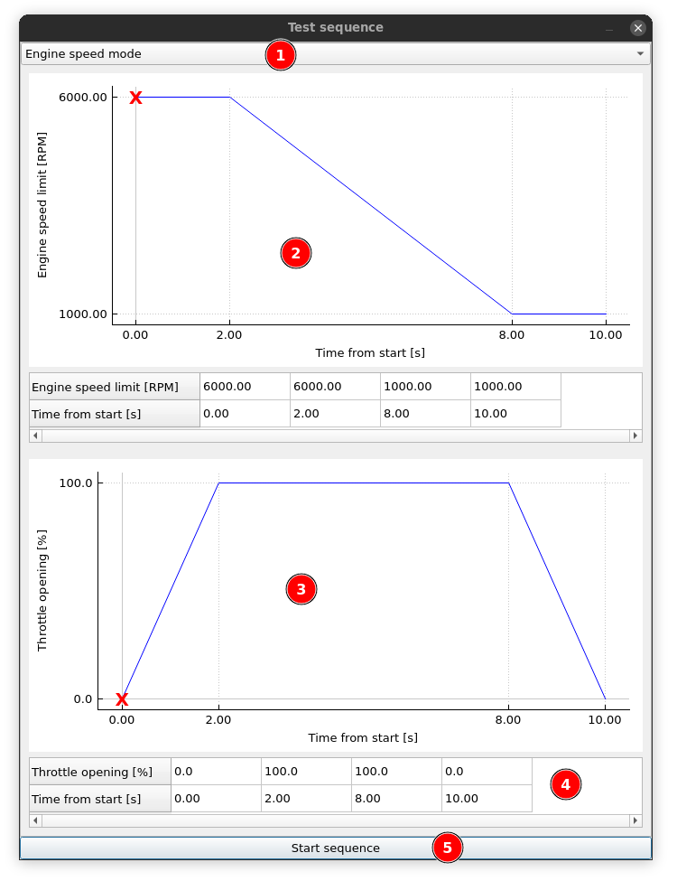
- Test sequence mode: engine speed or dyno speed
- Speed target area. It is used to control speed limit during the test. If the engine power is sufficient, the speed will follow this curve.
- Throttle opening target area. It is used to control throttle opening during the test. More details about throttle control setup can be found on the throttle control page.
- Table to edit sequence points. The software guards time values to be monotonic. This means that you can’t enter a bigger time value on the left of a lower time value. You need to increase or delete a value on the right first.
- Start sequence button. Pressing the button starts sequence playback.
Keyboard shortcuts used to edit the curves:
- Del – deletes curve point
- I – inserts new point to the left of the current one
- O – inserts new point to the right of current one
Curves can be saved and loaded in files by right-clicking the curve and selecting Save to file / Load from file.
Units and decimal point count can be changed by right-clicking the related axis on the plot and selecting the functions from the context menu.
Inertia calibration
Inertia calibration mode is used to record acceleration – deceleration loop to be used later in ANALYZE to calibrate the moments of inertia in the dyno.
Custom acceleration rate
With this test, the acceleration rate of the dyno can be controlled by any parameter you like. You can set it up to change at some engine speed or set a higher acceleration rate after boost builds up.
Custom torque
With this test, the torque of the absorbers can be controlled by any parameter you like. You can set it up to depend on the engine speed, boost pressure, throttle or any other parameter available in the software.
Sim connector
Sim connector test connects the throttle control and engine speed target to a racing simulator. This way engine operation can be simulated on any track available in the simulator.
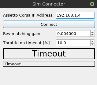
To use the connection, make sure that PC simulator IP and ports are accessible from the dyno controller (i.e. not blocked by firewall).
On the PC run the simulator, start the race.
On the dyno controller click connect and start the run.
The dyno controller will receive the throttle, gear and speed data from the simulator and execute them on the dyno.
If needed, adjust Rev matching gain to add extra throttle on the dyno, when vehicle is engine-braking in the simulation.
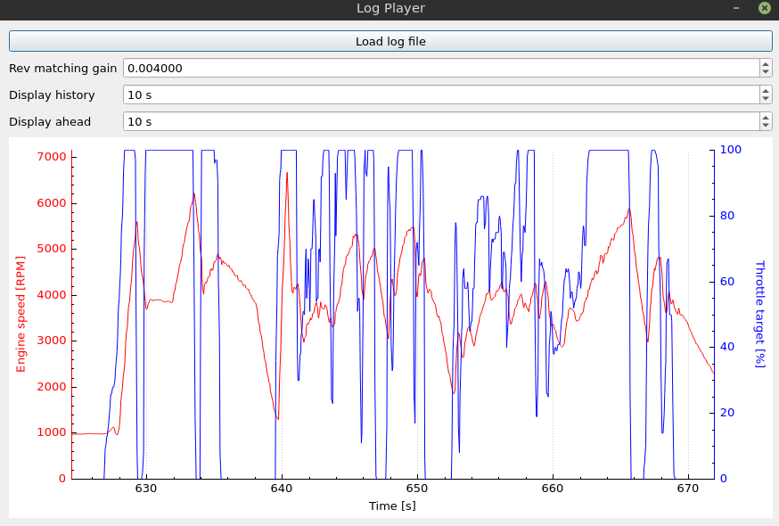
Log player
The log player lets you play back the log file from a car datalogger on the dyno. This way if you have a recorded data of your own runs on the track and something wrongs happen, you can simulate the race on the dyno and check how the engine is handling it. The log files should be in CSV format.
Rev matching gain is used to add extra throttle on the dyno to rev up the engine, when the vehicle was engine-braking in the log.
Outputs control
The output section of the application shows current output state and allows controlling their state.
Output configuration is available by right-clicking the output label.
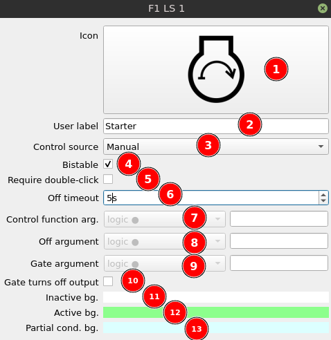
- Output icon
- Output label
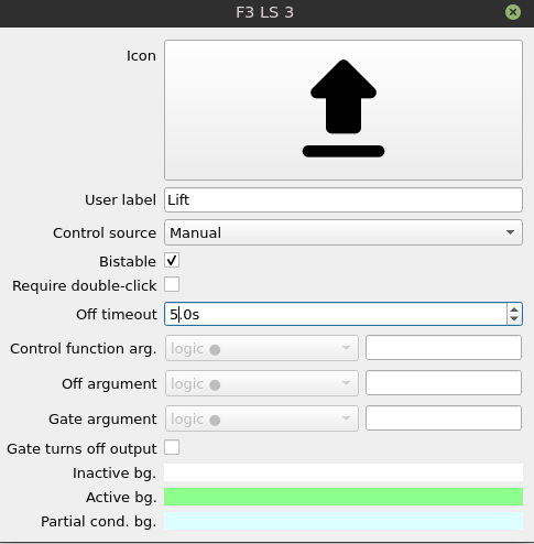
- Control source
- Manual – the output is activated with a mouse click on the output label. It can be also activated with press of a keyboard button (F1 – F8 from top to bottom). Output state can be monostable or bistable. Monostable output is active only when an activating signal is present (keyboard key or mouse button pressed). It is a good option for controlling starter motor. Bistable output state changes and latches every time it receives an activating signal.
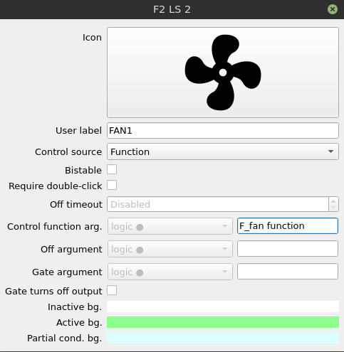
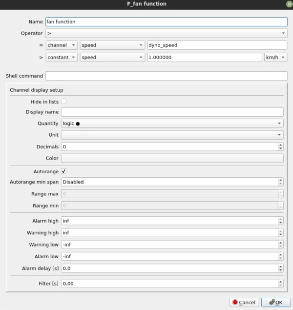
- Function – the output is controlled with programmable logic function. Functions can be created in SETTINGS / Functions tab.
- Manual OR Function – the output is active if logic function is active or if it is manually activated. Manual activation can still be monostable or bistable.
- Manual AND Function – the output is active if logic function is active and if it is manually activated. Manual activation can still be monostable or bistable.
- Bistable – check to set manual activation as bistable. Bistable output state is latched every time it receives an activating signal – key press or mouse click.
- Activate by a double not by a single click to avoid accidental activation whan using touchpad.
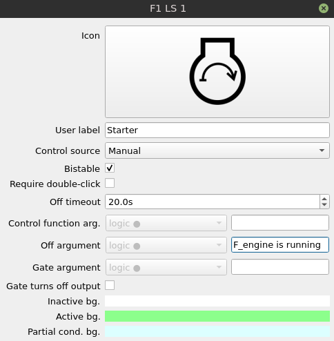
- Off timeout – if this option is activated (value higher than 0s), the output will be switched off timeout time after being switched on manually. This option switches off only the manual part of the (Manual OR/AND Function) logic.
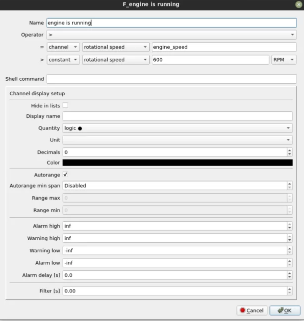
- Control function argument is the channel that is checked when the control source includes a function.
- Off argument – if this argument is set, the output will be switched off if the argument has an active value (true). This option switches off only the manual part of the (Manual OR/AND Function) logic.
- Gate argument is used to block changing the state of the output. It can be used for example as a protection to avoid activating an output when the dyno rollers are turning.
- Optionally if the gate argument is false, it can turn off the output.
- Button color when the output is inactive
- Button color when the output is active
- Button color when only a part of the “Manual AND Function” condition is met.
The function must have quantity set to “logic” to be available for selection in the output configuration.
Some example configurations are presented below:
Actuator widgets
The actuator widgets are suitable for controlling dyno devices that have two distinct positions. That can be for example lifts, roller coupling clutches or roller locking devices (electric parking brakes).
The actuator code operates as a state machine that go through following states:
- activating
- activation timeout
- active
- deactivating
- deactivation timeout
- inactive
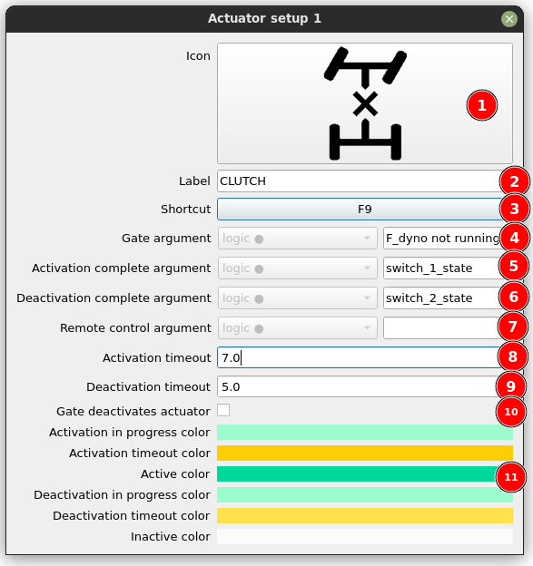
You can access the actuator configuration by right-clicking the actuator widgets. Available options are:
- Icon
- Label
- Shortcut
- Gate argument – the arguments that defines if actuator state change is allowed. It can be used to protect actuator movement when the dyno is running.
- Activation complete argument – this channel confirms that the active position has been reached. If not provided, the actuator will only use timeout time to switch to active state.
- Deactivation complete argument – this channel confirms that the inactive position has been reached. If not provided, the actuator will only use timeout time to switch to inactive state.
- Remote control argument – used to trigger activation or deactivation with external channel: switch, function or other condition.
- Activation timeout – used to stop the activation after a defined time if no feedback is provided by the “Activation complete argument”.
- Deactivation timeout – used to stop the deactivation after a defined time if no feedback is provided by the “Deactivation complete argument”.
- Gate deactivates actuator – if this option is checked, the true value of gate argument will trigger actuator deactivation.
- Color setup for all actuator states. The actuator widget will have the selected colors in background to indicate its state.
Actuator code can be connected with the system in the following way:
INPUTS:
The actuator is controlled with click on the widget, shortcut or by remote control argument.
The activation and deactivation is stopped by timeout or the “complete argument” (end switch or similar idea).
OUTPUTS:
The actuator provides three channels available throughout the dyno software system:
actuatorController_n_state – it’s the state of the actuator in form of number from 1 (activating) to 6 (inactive).
actuatorController_n_activate – convenience channel that has true value when actuator is in “activating” state. It can be used to drive output that activates the physical device.
actuatorController_n_deactivate – convenience channel that has true value when actuator is in “deactivating” state. It can be used to drive output that deactivates the physical device.
Typically, the activate and deactivate channels will be assigned to control relay or low side output, but these values can be also sent by CAN bus or used in other subsystem.
Setting up desktops and available widgets
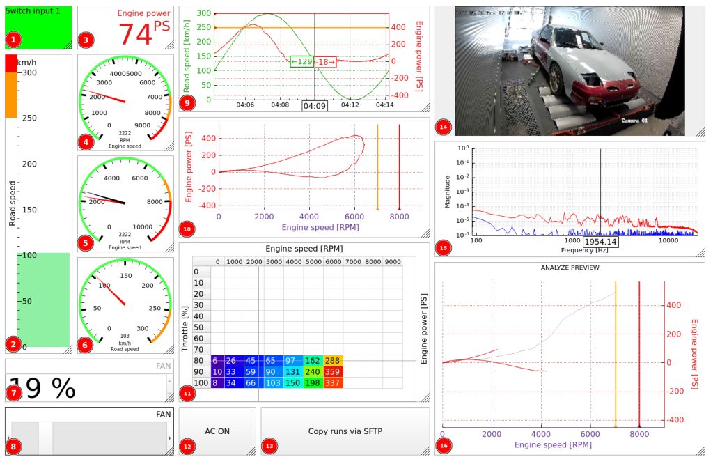
- Indicator – shows logic channel state by filling with selected color. It can also be set to indicate channel warning or alarm.
- Bar – shows channel value as color filled bar.
- Number – shows channel value as numeric value.
- Gauge – shows channel value as a gauge with needle pointing the value.
- Engine Speed Gauge – shows specifically engine speed channel and another needle pointing on current engine speed target.
- Road Speed Gauge – shows specifically road speed channel and another needle pointing on current road speed target.
- Input Spin Box – widget for changing value of UI input channel with numeric display.
- Input Slider – widget for changing value of UI input channel with a slider.
- Time Plot – plots data value as a function of time.
A time based plot shows selected channels as a function of time. On this plot, we can see for example recent speed and power values. Channel selection is made by right-clicking the plot axis to which we want to assign a different channel. Plotting can be paused or cleared during the run. Data retention time can be adjusted with Time history value in widget configuration. - Scatter Plot – plots data value as a function of another value.
Scatter plot allows analyzing relations between any data channels. These can be for example power and ignition angle. Channel selection is made by right-clicking the plot axis to which we want to assign a different channel. Plotting can be paused or cleared during the run. Data retention time can be adjusted with Time history value in widget configuration. - XY Table – mapps value of a channel as a function of other x and y channels. Can be used for mapping for example lambda value on the throttle vs engine speed map.
- Input Button – a button for changing value of UI input channel that has logic quantity.
- Command Button – a button for executing a system shell command.
- Camera – shows video from RTSP stream.
- Audio Spectrum – shows spectrum of audio signal. Usefull for finding engine knock frequency.
- Preview Plot – plots current power over the runs that are loaded in ANALYZE tab.
Widgets through the right-click give access to data channel configuration options. More details on channel configuration can be found in Dyno2 Dynamometer Software – data channels.