CAN outputs settings are used to send custom data on CAN bus – automotive multiplexed data bus. Basic information about CAN bus can be acquired from Wikipedia page on CAN. Sending data on CAN bus can be used to control external devices or to provide information for other systems working with dynamometer. For example, engine power can be sent to an aftermarket ECU for automated ignition tuning or just to be viewed and logged in the tuning software.
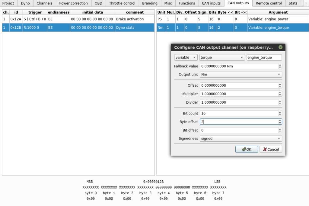
The left side of the configuration window contains frames that are to be sent on the BUS. After clicking the frame, right part of the window shows data channels that are exported to this frame. New frames and data channels can be added with New option available from right mouse click.
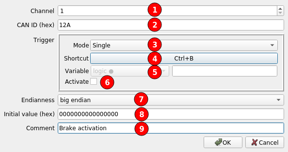
(1) Controller channel that is used to send the frame
(2) CAN frame ID
(3) Frame sending mode: Single or Repeat.
(4) Keyboard shortcut to send the frame
(5) Data channel that activates frame sending
(6) Manual activation of frame sending
(7) Frame byte order – Endianness
(8) Initial value of frame data, before channels data is written to the frame
(9) Comment
The above configuration is an example of a CAN message that can activate some external device function. It is triggered with a keyboard shortcut. The 12A frame is sent once on pressing the selected shortcut (Ctrl+B). In Single mode, a frame can also be sent once by clicking Activate checkbox.
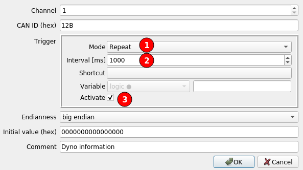
When sending data to other device we need to send it in Repeat (1) mode, so the device will always have fresh information. In this example, Interval (2) is set to 1000ms. The interval can be set as low as 10ms, what gives 100Hz refresh rate. Activate option (3) is checked to enable frame sending. The option (3) can be unchecked to disable sending of the frame. If frame should be sent conditionally, instead of fixed activation, frame sending can be activated with logic data channel.
After creating frame configuration, we select it on the list to display assigned data channels. To add a new channel we need to right-click on the right list and select New.
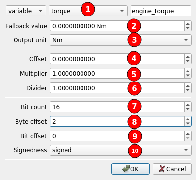
(1) Data channel that will be written to output frame
(2) Fallback value that is used when the channel is not available
(3) Unit that the data is converted to for export from internal SI units
(4) Constant offset added to output value
(5) Multiplier of output value
(6) Divider of output value
(7) Bit count to store the value in frame
(8) (9) Position used to store the value. The offset is always counted from the right side, from the least significant bit, after taking the endianness into account. Position = Byte offset * 8 + Bit offset.
(10) Defines if the extracted number will be interpreted as unsigned or signed. A signed number is a number that can have negative values. Two’s complement format is used for signed numbers.
Output number = (Unit_Conversion(channel_value) + Offset) * Multiplier / Divider
If, after conversions, the value is greater or lower than the value that can be fit in the selected Bit count, the value is clamped to the minimal or maximal value that can fit.