When purely inertial dyno is used, the calculated power on wheels is directly proportional to the inertia value entered in the calculation:
Power = rotational speed * rotational acceleration * inertia
Inertia value has direct influence on measurement result. It’s worth mentioning, that inertia of all bodies accelerating during the run is required for accurate result. If these bodies are rotating at different speed than dyno roller shaft, their inertia should be multiplied by the speed ratio squared. This is especially important in case of chassis dyno, where vehicle drivetrain bodies rotate with dyno roller. If dyno inertia is calculated, it’s more important to think about typical inertia of vehicle wheels and shafts than to focus on roller bearings inertia.
In the Dyno2 software, there are multiple places that contain information about inertia of rotating bodies.
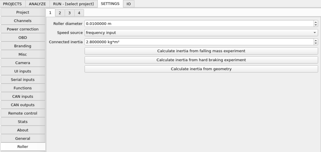
- SETTINGS / Roller / n / Connected inertia – here you must enter rotational inertia information about your dynamometer. Each of these is associated with particular rotational speed and acceleration from controller frequency input.
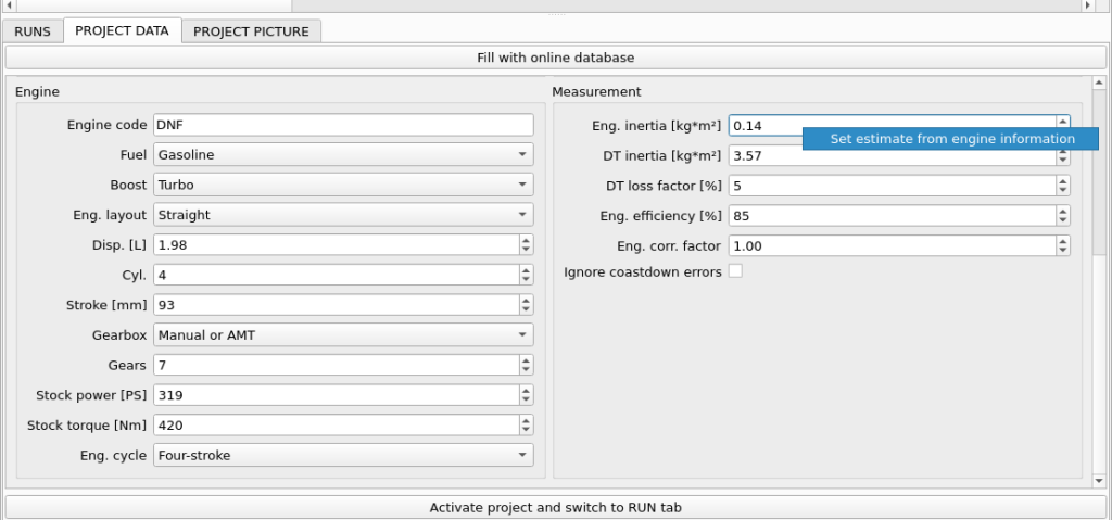
- PROJECT / Eng. inertia – this inertia has same meaning as inertia in Frequency Input 3 (Engine speed). Both inertia values are summed for calculation. This is the preferred place for engine inertia, as it should be adjusted for every project. The value here should represent inertia of all engine rotating elements up to clutch, transferred to crankshaft. Typical engine inertia is roughly related to displacement and can be automatically filled in by right-clicking the field in PROJECT DATA.
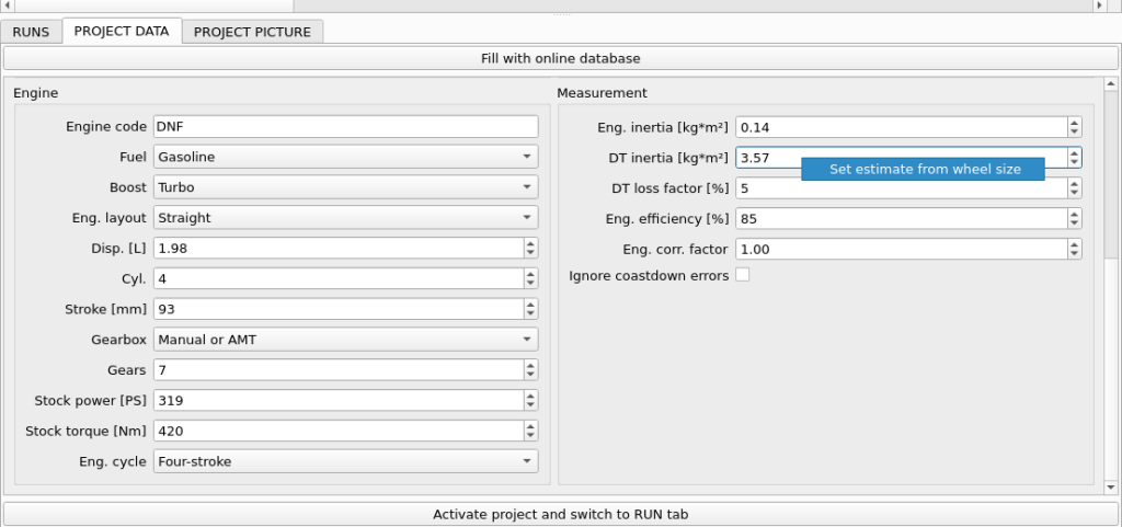
- PROJECT / DT inertia – this is the value of inertia that is associated with car drivetrain – from clutch up to and including wheels. The inertia must be recalculated as inertia transferred to first roller rotational speed. The most important part here is played by wheels, which have the biggest diameter of all elements. The drivetrain inertia also plays an important role in overall inertia dyno result.
Here is an example of dyno and inertia that play a part in calculations:
Let’s take example chassis dyno: 2WD, 30cm roller diameter.
The rotational inertia of this set is somewhere around 10kg*m². This value should be entered in SETTINGS / Roller / 1 / Connected inertia
Now we put a small car on this dyno: Toyota Yaris 1.0l, 175/65R14 wheels.
Engine inertia for 1.0l engine is somewhere around 0.15kg*m². This value, transferred to roller with speed ratio 2.0, gives 0.6kg*m². It’s 6% of our rollers inertia.
Wheels inertia transferred to roller for this car is around 0.4 kg*m². It’s 4% of the rollers inertia.
If the car inertia from this example is omitted on our inertial dyno. The dyno would show only 91% of our car real power (we take friction losses out of the equation for simplicity).
Now you think: OK, let’s put all this inertia into dyno inertia and forget about it. One of the problems with this thinking is that the engine inertia is disconnected from the dyno on loss calculation. This in 6% error in loss calculation. Another problem is the next car on our dyno: Ford F150 5.0l.
The rough estimate of the engine inertia would be 0.5kg*m². For the massive 265/70R17 wheel set, it will be around 8.5kg*m². As you can already see, that are some significant additions to our dyno inertia.
All this inertia information can make us very sad about measurement accuracy on our dyno. There are however some points to make things better:
- We only want to tune our car to have more power. The absolute value is not that important. We are OK, because with the same car on our dyno, horsepower measurement precision (not accuracy), will be fine, even with some unknown inertia values around.
- We want our rollers to have as much inertia as we can sanely put in our dyno. If we get a huge 100kg*m² roller set, the Ford inertia effect will reduce.
- We can use inertia estimations available in Dyno2 software. These are only estimations and real values can be a bit different, but it’s better to use these than to completely ignore the problem.
- If we can afford an absorption dyno that can hold our F150 on constant speed, the inertia problem in calculation of power on wheels disappears as the 0 acceleration in power equation results in 0 power from inertia. All the power is measured on the absorber load cell. There is a catch, however. Inertia information is required for loss power calculation to get engine power estimation.
Equivalent roller mass inertia
The roller rotational moment of inertia stated in kg*m² is a parameter that is directly used by the software to calculate torque and power from roller rotational speed and acceleration. Is it a good parameter to compare dynamometers? It seems that it should be, but on dynos with bigger diameter rollers the roller rotational speed and acceleration is lower, and thus the rotational inertia effect is reduced. So what’s the other way to compare dyno rollers? You can calculate a linear motion inertia mass equivalent to the rotational moment of inertia. To do this, we use the equation for rotational inertia, assuming that the whole equivalent mass is placed at the surface of the roller: I = mr². Transformed equation gives us the equivalent mass: m = I/r². This value gives us a very nice feel of how the car will behave on the dyno, because it’s an equivalent of the vehicle mass when accelerating on the road (not accounting for air resistance). Here are some examples:
| Moment of inertia [kg*m²] | Diameter [m] | Equivalent mass inertia [kg] | Notes | |
|---|---|---|---|---|
| 2 wheels 175/65/R14 | 1.3 | 0.583 | 15 | Not including the ordinary mass |
| 2 wheels 265/70R17 | 8.5 | 0.803 | 53 | Not including the ordinary mass |
| Dynocom Dyno X | 2.6 | 0.216 | 223 | |
| Maha LPS 2000 | 7.4 | 0.32 | 289 | |
| Mustang MD-1750 | 462 | 1.27 | 1146 | |
| 2WD hub dyno on KLAM CFK-550 | 9.5 | 0.6 | 106 | Assuming the vehicle had a 0.6m diameter wheel |
| 2WD hub dyno on Frenelsa F16-160 | 4 | 0.6 | 44 | Assuming the vehicle had a 0.6m diameter wheel |
Here or some key points to take from this table:
- Wheel inertia again… don’t assume all cars are the same. Skipping the fact of different inertia of different wheels will easily introduce few percent of error to your dyno measurements.
- Equivalent mass of the rollers should be chosen to simulate road conditions well. Not too low, but making it too high have some downsides too. Dynocom Dyno X will let you simulate acceleration of vehicles weighing from 223kg up. The absorber provides the rest. On a Mustang MD-1750 you won’t be able to simulate acceleration of a vehicle weighing less than 1146kg. If you’re making an inertial only dyno, go for equivalent mass similar to typical vehicle mass. If you’re making a braked dyno, go for lower equivalent mass to make the device more versatile.
- Hub dyno has relatively low equivalent mass. This makes the system behave like a very light vehicle. Small difference between vehicle torque and the opposing absorber torque creates high acceleration. That’s the reason it requires the use of fast eddy brake interface like the PEREK BD3 to perform well. Imagine how a 200PS, 100kg vehicle behaves versus a 200PS, 1000kg vehicle.
What about dyno absorbers? Is it possible to calculate equivalent mass from the absorber torque? This is a bit more complicated as the equation result depends on the vehicle power. In other words: Until your absorber have enough torque to hold the vehicle at steady speed, it’s like having an adjustable extra equivalent mass from 0 up to infinity.
Roller inertia / weight selection for chassis dyno
When designing a new dyno this is one of the most frequently asked questions: How heavy should my dyno rollers be? Well, that depends on the dyno type and planned usage. Let’s go through some of possible options.
We can’t talk about rotational moment of inertia without the roller diameter. Big diameter roller will have high moment of inertia, but it will rotate slower. It will perform the same as the roller with smaller moment of inertia and smaller diameter. To eliminate the diameter from these considerations we will talk about Equivalent Mass, which I will label EM. I will also relate to mass of vehicles tested on the dyno. The lightest vehicle we plan to test will have Vehicle Mass VMmin and the heaviest VMmax.
In braked dyno case we are able to add extra load with the absorber, so heavy roller is not required. However, some mass is required to smooth the measurement and give the absorber time to react to change in vehicle power. If we plan to own a braked dyno we probably will want to do road simulation. To be able to do it, our rollers can’t be too heavy, because then the vehicle won’t be able to accelerate as fast on the dyno as it does on the road. From this we formulate requirement EM < VMmin. Also as mentioned before we benefit from high EM. So you should choose EM close, but less than VMmin.
In inertial dyno we can’t add any extra load, and we won’t be able to do road simulation anyway. The main problem we can encounter is that the roller will be too light, and the vehicle will accelerate much faster than on the road and the turbo won’t spool to the boost it can achieve in real road condition. Another problem is the accuracy associated with the uncertainty in the inertia of extra elements that come with the vehicle. Our condition for this type of the dyno will be EM > VMmax. One last thought is that when we go with EM much higher than VM, then the vehicle will accelerate on the dyno much slower than on the road, and it will be a waste of time.
Here is some quick sum up in form of rough guidelines for EM:
Braked car dyno: 200kg – 500kg
Inertial car dyno: at least 1000kg, preferred: 1500kg-2000kg
Braked motorcycle dyno: 50kg
Inertial motorcycle dyno: at least 150kg, if we work with high power turbo motorcycles preferred would be 300kg-400kg
Equivalent mass to roller mass conversion
The precise way to calculate the equivalent mass would be to calculate first the total moment of inertia of the roller, shafts, absorbers and then use equation EM = I/r²
For quick estimation we can take some shortcuts. Let’s label roller mass as RM.
For a roller made of pipe if we assume the wall thickness is much smaller than radius and neglect the extra parts like end plates and shafts, the moment of inertia is I≈m*r². Then the EM ≈ RM.
For a full roller the moment of inertia is I=0.5*m*r². Then the EM ≈ 0.5RM.
So if we decide to use full roller, it must weigh twice as much as the pipe roller to get the same performance.
Flywheel calculator for inertial engine dyno
For an inertial only engine dyno we can calculate the required flywheel from the engine power and desired run time. Typically, to get a good measurement resolution we need a run time around 10s. This calculator assumes that the engine has a constant torque throughout the speed range.
Peak engine speed
RPM
Peak engine power
PS
Desired run time
s
Engine to flywheel speed ratio
Required flywheel moment of inertia
kgm²
Inertia calibration methods
- Reading of inertia from dyno CAD model.
- Inertia calculation from physics experiment – three-wire pendulum, ramp roll down
- Performing inertia calibration experiment and using one of Dyno2 software tools.
- Making a double ramp test – two engine characteristic measurements – one purely inertial and one with absorber.
- For amateur dyno, where precise dyno calibration is not required, the dyno can be calibrated by making measurement of power of a vehicle with known power. The vehicle power can be confirmed on other calibrated dyno and then the measurement on our dyno can be made. Our dyno inertia should be corrected using equation below: correct inertia = current inertia * real power / measured power
Inertia effect on absorption dyno
When absorption dyno is used, engine power is calculated using brake torque measurement and torque calculation resulting from inertial body acceleration. In inertia in our setup changes often or there is no way to estimate it, accurate measurements can still be achieved by minimizing or completely eliminating dyno acceleration. If in the dyno equation
Power = rotational speed * rotational acceleration * inertia
the rotational acceleration will be 0, the power associated with inertia will not take part in the final result.
Falling mass inertia calibration tool
If you have a braked dyno, better use double ramp or hard braking method.
The tool is available in SETTINGS / Roller / n / Calculate inertia from falling mass experiment
Dyno inertia can be measured without sophisticated equipment by conducting a simple experiment.
- Before starting the procedure, roller diameters must be set up correctly.
- If you choose this method on braked dyno, the measurement should be done with load cells disabled.
- Some initial inertia value needs to be set for the loss model to work. You can set 1kgm².
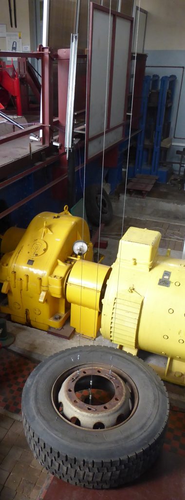
- Tape a thin rope to one of the rollers. It should be taped in a non-permanent way. When the rope would unwind to this spot, it should disconnect.
- Wind the rope on the roller and route it through a pulley located in a high spot.
- Hang an object of known mass at the end of the rope. The object mass should be significantly higher than the mass of the rope.
- Start the measurement by clicking START button and release the object. It should accelerate the roller set. The rope should disengage from the roller before the object hits the floor.
- The roller set should freely slow down to a stop and the measurement should be stopped.
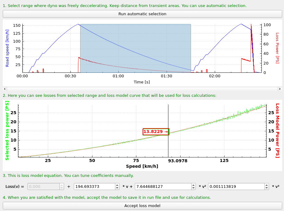
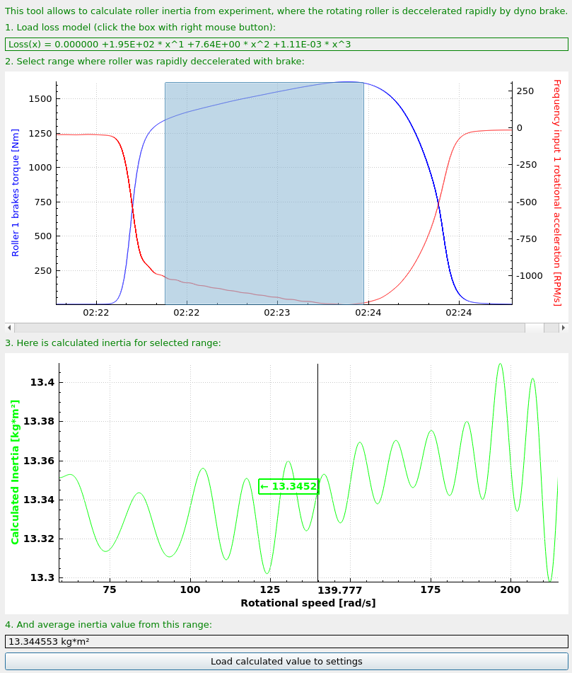
- Open the measurement with the calibration tool.
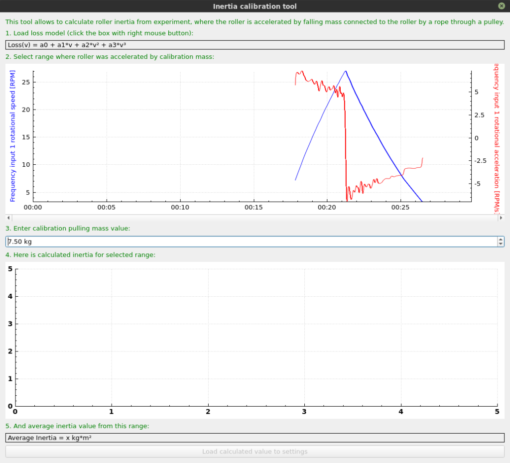
- If the loss model is not calculated in the run, it should be calculated by right-clicking on it and calculating it as described. Pay no attention to loss power values, as this have no meaning until inertia is calculated.
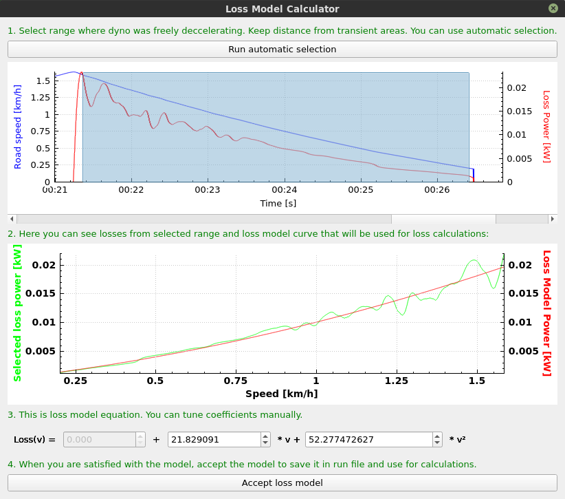
- Enter the mass of the object which was accelerating the rollers, and select the part of measurement with constant acceleration.
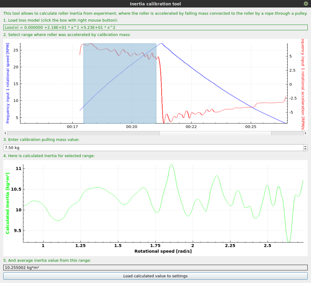
- Calculated average inertia will be displayed in the lower part of the tool.
- The inertia can be loaded to the settings by clicking Load calculated value to settings button.
Hard braking inertia calibration tool
The tool is available in SETTINGS / Roller / n / Calculate inertia from hard braking experiment
In case of absorption dyno, the inertia can be estimated by braking with full power of the brake while measuring braking torque and roller deceleration.
Rotational inertia = (absorber torque + friction torque) / roller deceleration
Absorber torque is known from absorber load cell.
Friction torque can be estimated from free roller deceleration with use of loss model calculator.
- Before starting the procedure, roller diameters and load cell coefficients must be set up correctly.
- Some initial inertia value needs to be set for the loss model to work. You can set 1kgm².
- Start the measurement by clicking the START button.
- Accelerate the roller to high speed.
- Wait for the roller to stop freely.
- Accelerate the roller to high speed again.
- Set full brake power in manual mode.
- STOP the measurement.
- Open the measurement with the calibration tool.
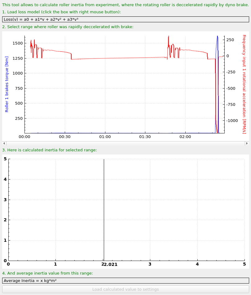
- If the loss model is not calculated in the run, it should be calculated by right-clicking on it and calculating it as described.
- Select run section where brake was on full power.
- Calculated inertia is available below.
Keep in mind that if you are accelerating the rollers with the vehicle, and the vehicle is still on the rollers during hard braking, the inertia shown is a sum of dynamometer inertia and vehicle inertia.
Double ramp calibration
Double ramp inertia calibration is one of the easiest ways to calibrate dyno inertia on absorber dynamometer. To perform the calibration, you need a vehicle with a repeatable naturally aspirated engine. The idea of the calibration is to compare two tests where inertia plays different part and adjust it to get the same result.
- Warm up the engine and make some consecutive tests to be sure that the results are repeatable.
- Make a test with heavy absorber load: slow acceleration ramp or even negative ramp from top speed to bottom.
- Immediately after, make a purely inertial test with brake off.
- Load both tests, heavy load and inertial, to ANALYZE.
- Run the calibration tool by right-clicking the run on the list and selecting “Double ramp inertia calibration”. Do the same with the second run.
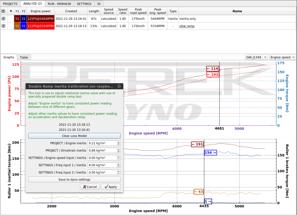
- “Engine inertia” and “Drivetrain inertia” are already set up from PROJECTS tab based on our engine displacement and tire size. The only value that will be adjusted is “SETTINGS / Roller 1 / inertia” which is the inertia associated with our rollers.
- Press “Clear Loss Model” to be sure that the speed based losses won’t interfere with the process. The runs were made one after another with a warmed up car, so the losses are comparable.
- The purely inertial run shows a higher power result. That’s the indication that the inertia is too high.
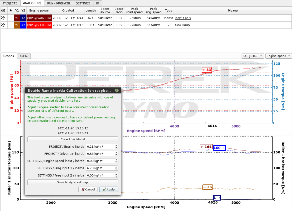
- Adjust “SETTINGS / Roller 1 / inertia” and click Apply to get matching power curves.
- When confident that the settings are tuned, click “Save to dyno setting” to save the settings for further runs. Apply button only saves the settings for the runs you’re working on.
- Close the tool with X button.
Three wire pendulum experiment
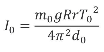
Vehicle wheel can be precisely measured by creating a three wire pendulum with the wheel and measuring the oscillation period of the pendulum.
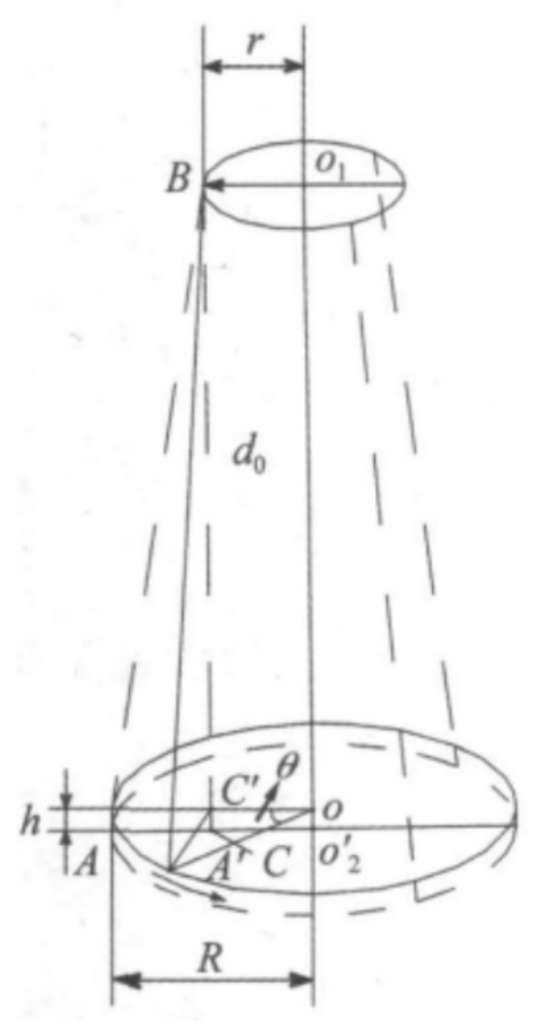
m0 – mass of wheel
g – gravitional acceleration – 9.8m/s²
R – radius of wheel suspension points
r – radius of top suspension points
T0 – period of oscillation
d0 – vertical distance between top suspension points and wheel suspension points in equilibrium state
To perform the experiment the wheel should be hanged on three wires from a suspension point. The wheel should be rotated out of equilibrium by less than 6° and the period of the motion should be measured. With the use of equation presented earlier, wheel weight and movement period, the inertia can be calculated.
The wheel can be hanged directly on the wires or can be placed on a disk. When disk is used the experiment shows the total inertia of disk and wheel, so the disk inertia should be measured separately to be subtracted later from the total inertia.
More detailed description of the method can be found here:
https://www.happresearch.com/blog/2018/2/18/trifilar-pendulum-for-moi