DC1 series controller with Dyno2 dynamometer software offer functionality to control engine throttle directly from the software. Desired throttle opening can be entered directly in RUN tab or programmed as a test sequence together with absorber control speed target.
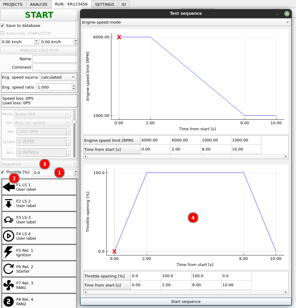
- Throttle target input field. Here, you can enter the desired throttle opening target.
- Enable checkbox. This checkbox must be checked to enable updating of “Throttle target” channel.
- From this box you can gain access to test sequence dialog (4) where you can set desired throttle opening curve during your test sequence.
- Throttle curve in test sequence dialog.
Now, when we know how to set the desired throttle target, we need to route it to some output that will pass it to the actuator. The value is available in “Throttle target” channel and there are many ways to use it. Let’s go through two examples.
Throttle control via PWM low side output that controls RC servomotor
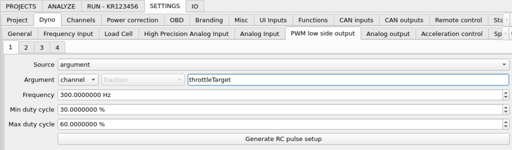
To make the configuration from scratch:
- Set Source: argument
- Set Argument: channel
- Double click channel value on the right of the Argument and select throttleTarget channel.
- Click Generate RC pulse setup to generate default frequency and duty cycle settings that are compatible with standard RC (remote control) servo motors.
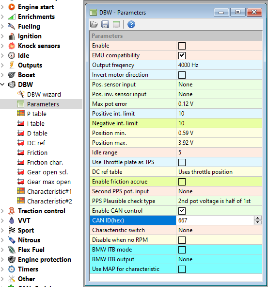
Throttle control via CAN bus message on example of Ecumaster EMU Black standalone ECU
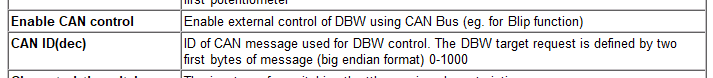
First, we need to make required configuration in the ECU software. Throttle control must be enabled in the EMU Black software by checking Enable CAN control option in DBW – Parameters. CAN ID must be the same in dyno controller and the ECU.
Throttle control in connection with Ecumaster EMU Black engine control unit is possible. To use the control, CAN channel (physical output) that is connected with EMU Black must be selected in SETTINGS / Throttle control
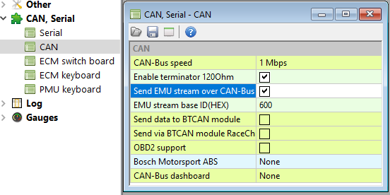
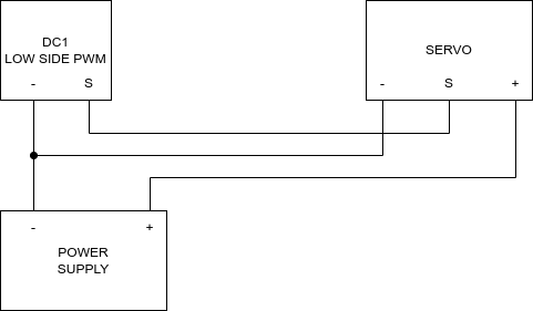
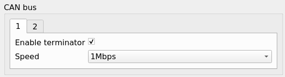
The CAN bus must be set to the same speed in both devices and must be equipped with terminating resistors. It is possible to enable built in terminating resistors with software in both devices.
In the next step, we need to set up CAN bus output that will send throttle target via CAN to the ECU. The preset for EMU Black is available on the application server and can be easily imported when internet access is available. To import the preset, go to SETTINGS / CAN outputs, right-click on the left table and select Import from website. From the list, select “EMU Black Throttle Control”.
The throttle control is now ready to use, but let’s analyze the imported setup. When we double-click the message in table on the left, the configuration window shows up.
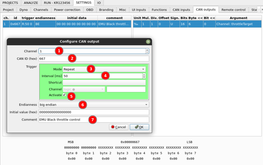
- The control message will be sent on the first channel of the DC1 controller.
- The ID of the can message is 667h – the same as in ECU configuration software.
- It is sent in repeat mode.
- With 50ms interval.
- The message sending is activated.
- Message format is big endian as per Ecumaster specification.
- The message has appropriate comment for future reference.
The CAN message contains only one channel. Let’s double-click it in the table on the right to check what’s under the hood.
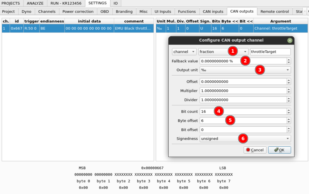
- Source for the CAN channel it dyno channel with fraction quantity and key throttleTarget.
- The fallback value it the channel is not set up is 0%. You can set it to 3% if your application require it.
- Output unit is set to permille what is sufficient to satisfy format specification (0 – 1000 value). Offset, multiplier and divider are left default.
- The value occupy 2 bytes (16 bits).
- The value must be in the first two bytes of the big endian message, so the required offset from the right is 6. We can preview our bit count and offset settings in the bottom part of the window.
- Signedness it set to “unsigned” but since the value has two bytes and goes only to 1000, both options would work.