Serial input module in Dyno2 software provides a way for communication with devices providing data via serial interface like RS-232. You can find that lots of professional exhaust gas analyzers provide serial interface to read multiple information about exhaust gas composition.
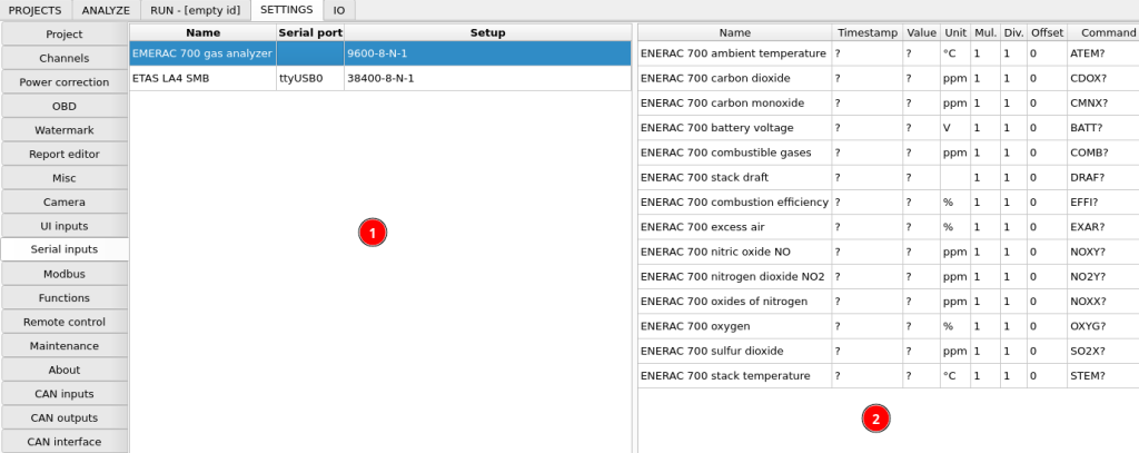
The left side of the configuration window contains serial input devices. Usually serial protocols are designed to make connection from one master to one slave, so if you want to connect multiple different devices, every one of them will have a separate RS-232 adapter. After clicking the interface, you can edit channels assigned to it in the right part of the window. Relevant options to add and remove device and channels are available under right-click.
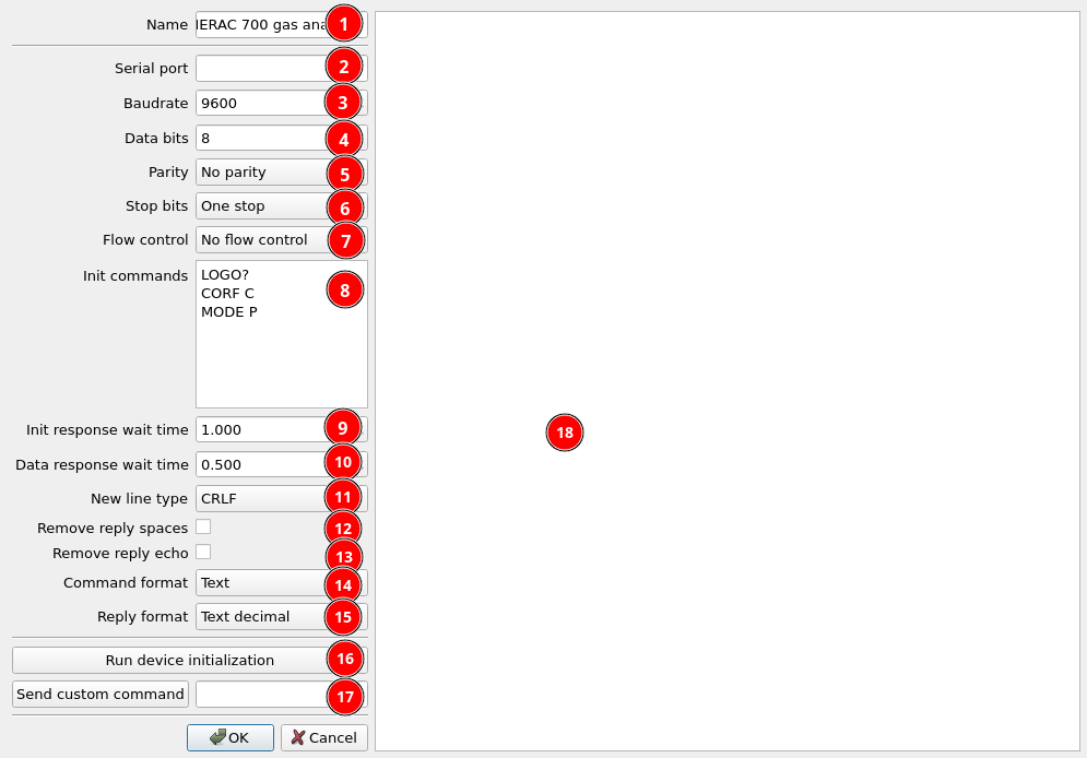
- Device name
- Serial port adapter – right click to see available adapters
- Baudrate
- Data bits
- Parity
- Stop bits
- Flow control
- Init commands – list of commands that will be sent to your devices once at the start to configure it
- Init response wait time – time to wait for response after init command
- Data response wait time – time to wait for response after each channel data request
- New line type – how each line command should be terminated
- Remove reply spaces – removes whitespace characters from reply before parsing
- Remove reply echo – some devices send command echo with data. It should be removed before parsing data.
- Command format – text or binary hexadecimal
- Reply format – text or binary hexadecimal
- Run device initialization – test initialization commands
- Custom command – here you can quickly send some custom data on the bus to see the response
- Serial communication log
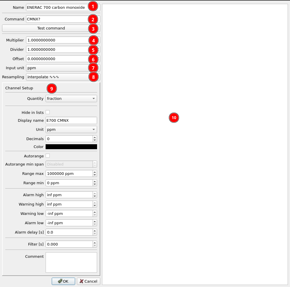
- Channel name
- Command text of value
- Test command button to check how it works
- Multiplier
- Divider
- Offset
- Input unit
- Resampling – resampling strategy – interpolate or sample and hold
- Common channel display setup
- Serial communication preview
The input value is calculated the following way:
Input value = Unit_Conversion(raw data number * Multiplier / Divider + Offset)