Internal combustion engine power output depends on intake air temperature and pressure. If you go with your car to dyno in freezing winter cold, it will produce more power than in the heat of summer. This also applies to dyno shops at the sea level and high in the mountain country, or just high and low barometric pressure day. To enable comparison of dyno engine power results between measurements made in different ambient conditions, power correction standards were created. The goal of the correction standard is to answer the question: What power will this engine generate in standard ambient condition if it produces X power in current conditions.
Each correction standard has different ambient conditions defined as reference, so to compare the results, you need to be sure you’re comparing results with the same correction standard.
For popular SAE J1349 standard, reference conditions are:
Dry air pressure: 990mbar
Temperature: 25°C
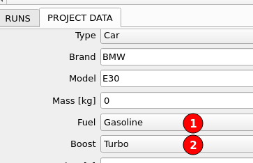
The exact equation used for the correction also depends on engine type. Is it spark or compression ignited? Is it naturally aspirated or turbocharged? All these details have to be filled in the project settings (1)(2).
Ambient conditions sensor in DC1 series controllers
For the purpose of engine power correction, DC1 controller has built in ambient conditions sensor. The sensor measures ambient temperature, pressure and humidity. Humidity is used to calculate dry air pressure required in standards equations from measured air pressure.
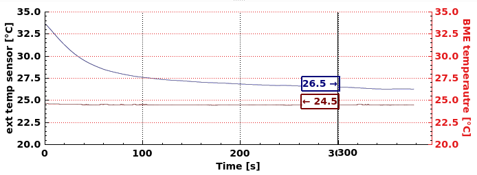
The sensor is installed inside the DC1 just under the cooling fan, so it is maximally exposed to external air. It is also isolated from the main board to reduce heat transfer from hot electronics inside the controller. This solution is satisfactory for most users as the sensor ultimately reaches temperature around 1.5°C higher than ambient and temperature difference of 2C in 300s after fan start on hot device.
This test was made in standing air with an external temperature sensor 20cm away from DC1.
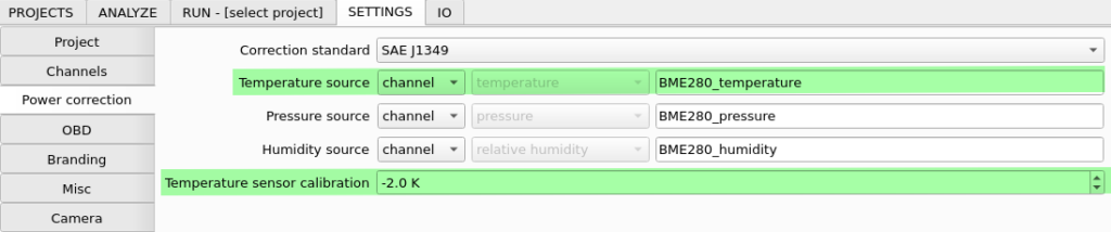
When the user has more strict temperature measurement requirements or the controller is placed inside a control cabinet which has temperature higher than ambient, external temperature sensor can be used. The premade sensor is available at our shop. Furthermore, all the ambient conditions can be sourced from any of the available dyno channels: analog inputs, CAN bus channels, OBD or manually entered values.
If the controller has stable operating conditions, internal sensor temperature difference can be compensated with temperature sensor calibration parameter.
For those concerned about cooling fan changing the pressure reading: Tests with fan ON vs. OFF showed change of pressure reading lower than 0.005%.
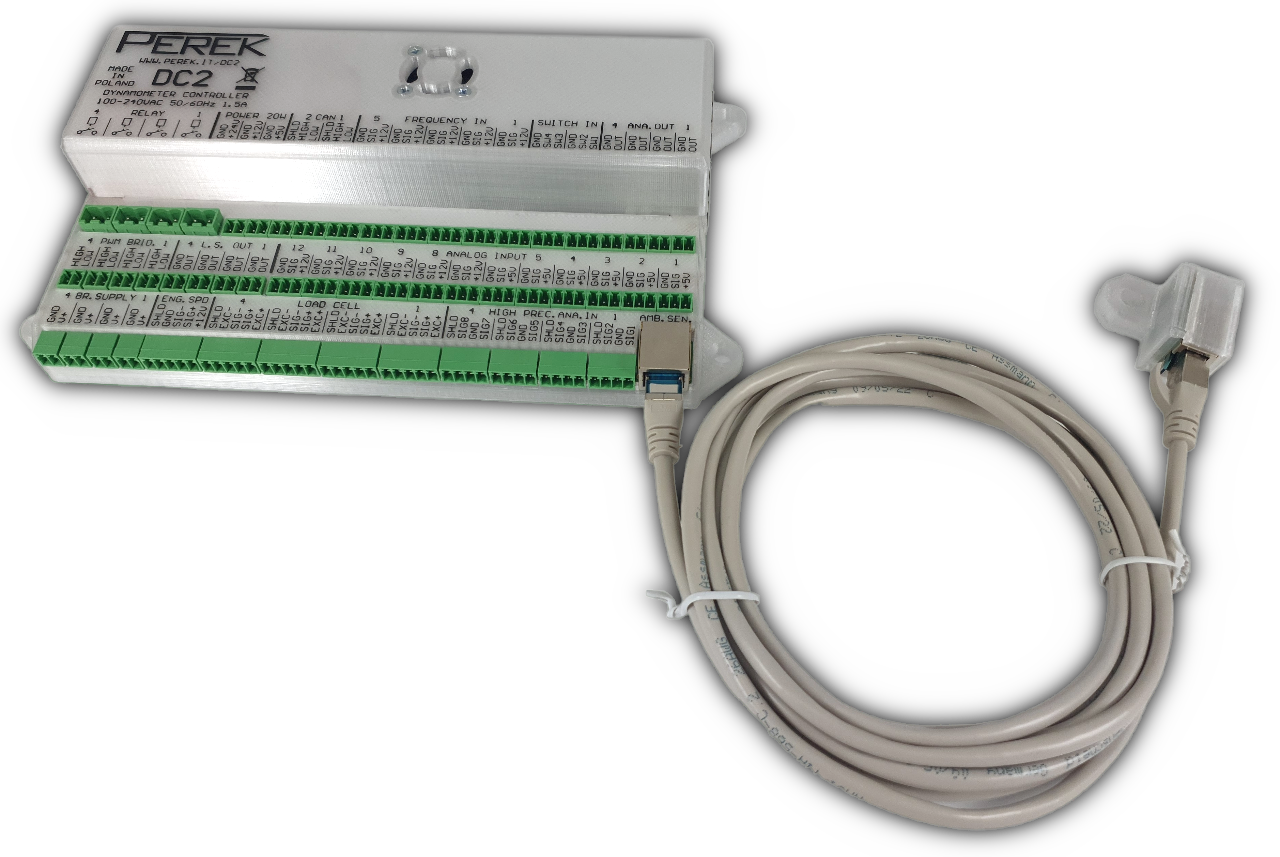
Ambient conditions sensor in DC2 series controllers
In DC2 series controllers, the ambient conditions sensor is a separate unit connected via cable to the main controller. It can be placed in the dyno cell away from any sources of pressure or temperature fluctuations.
Supported correction standards
Dyno software supports following correction standards:
- DIN 70020
- EC 95-1
- ISO 1585
- JIS D1001
- SAE J1349
- SAE J607
- EEC 80/1269
- FOS 2-stroke