The dynamometer software is controlled mainly through user interface with use of mouse and keyboard. It can also be controlled via CAN bus or physical buttons. Remote control configuration is configured in SETTINGS / Remote control. This functionality also allow setting up custom keyboard shortcuts for software actions.
Some examples of how remote control can be used:
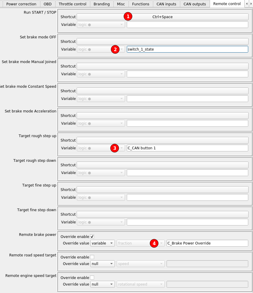
(1) Data logging START / STOP can be triggered with Ctrl+Space keyboard shortcut.
(2) Dyno absorber control can be switched to OFF mode with a physical key connected to Switch Input 1 of the controller.
(3) Current controller target for brake control loop can be incremented with a button that sends CAN bus message.
(4) Current absorber power can be overridden with a value received through CAN bus or custom function.
Remote control from Windows or Android app
Since version 4.3.0 it is possible to control the dyno through the Dyno2Remote Android app.
The app can be downloaded here.
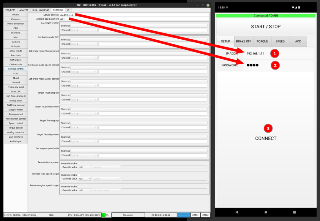
To use this functionality, the dyno controller and the phone or Windows PC must be connected to the same local LAN network. To set up the app:
- Enter server address
- Enter password
- Click connect
If everything goes OK, the bar at the top of the app should highlight in green color. The most probable source of failure is that the devices are not connected to the same LAN or that the IP address is misspelled.
The app allows controlling the basic dyno functionality from your android phone. The same restrictions apply to the app usage as to the Dyno2 software interface. For example, to be able to start the run, the RUN tab must be active in the Dyno2 software.
- Connection status – green when connected, red when there is no connection
- START / STOP button – when clicked in Android, makes a click on the START / STOP button in the Dyno2 software.
- SETUP and brake controller mode tabs – switching between tabs changes brake control mode
- Target rough step up
- Target fine step up
- Target fine step down
- Target rough step down
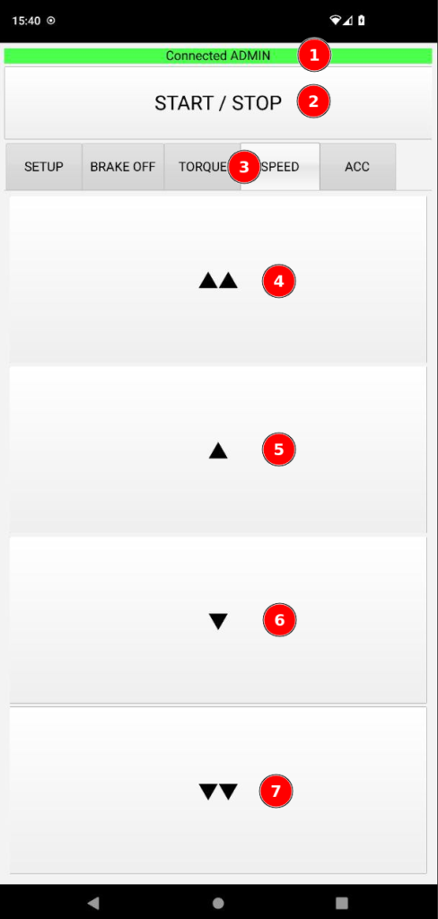
Step values can be configured in Dyno2 software by right-clicking the target values editors for each mode in RUN tab.
Remote control server API
The remote server that is used as the remote control app interface can also be used as an API for your own application. You can connect to the server using following data:
Server address: The controller IP address that is also listed in SETTINGS / Remote control
Server port: TCP 12369
As soon as you connect with the server, you will receive “HELLO” text.
Communication with the server is based on plain text commands and responses.
All command must be finished with ‘\n’.
All responses are finished with ‘\n’.
Correctly interpreted commands are replied with “OK“.
Not recognized commands or commands with syntax errors are replied with “?“.
Commands requiring admin privileges when PASSWD was not provided before are replied with “NOT-ADMIN“.
The following commands are supported:
PASSWD <SHA256 hash of password from SETTINGS / Remote control>
Responses:
PASSWD OK – the password is correct
PASSWD NOK – the password is incorrect
To protect the dyno from damage by an unauthorized user, the API provides only access to channel reading without logging in with the password. All other commands will be rejected with NOT-ADMIN response if a correct password was not provided at any time before the command.
CHANNEL <URL encoded channel key>
Example:
CHANNEL engine_correctedPower
Responses:
CHANNEL <channel value>
CHANNEL NOT-FOUND – the channel with provided key not found
The command provides current channel value in SI units. The channel keys are the ones listed in the left column when you select a channel to display in widgets or on graphs. The channel key must be URL encoded.
WRITE-CHANNEL <URL encoded channel key> <value in SI unit>
Example:
WRITE-CHANNEL I_my%20input%20channel 15.97
Responses:
OK
CHANNEL NOT-FOUND – the channel with provided key not found
This command can be used to write a value ONLY to the channels that are added in SETTINGS / UI inputs. Overwriting other channels will fail with NOT-FOUND response. Keep in mind that the input channel key is generated by adding “I_” prefix to your channel name.
START-STOP
Equivalent of clicking on the START / STOP button in RUN tab.
SET MODE <BRAKE-OFF | TORQUE-JOINED | SPEED | ACC>
Switches the brake control modes of operation.
SET <TORQUE | ROAD-SPEED | ENGINE-SPEED> <value>
Example:
SET TORQUE 0.25
Sets the brake control setpoint value. Torque is set as a fraction of maximum available torque. Road speed in [m/s]. Engine speed in [rad/s].
STEP <UPUP | UP | DOWN | DOWNDOWN>
Steps the brake control setpoint value up or down by a fine or rough step.
KEY <F1 – F12> <PRESS | RELEASE>
This command has the same effect on the software as pressing or releasing F1 – F12 key on the keyboard. It can be used to control outputs or actuators in RUN tab.
TAB <ANALYZE | RUN>
Switches main software tabs.
ANALYZE
Triggers “ANALYZE LAST RUN” action.