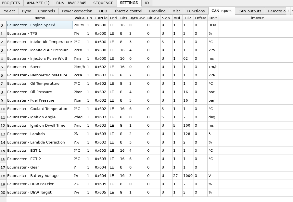
CAN inputs settings are used to extract data from CAN bus – automotive multiplexed data bus. Basic information about CAN bus can be acquired from Wikipedia page on CAN. Extracted data can be plotted on charts or used to control device outputs. Configured data channel sets can be exported to and imported from files. Ready configuration sets for most aftermarket ECUs are available here.
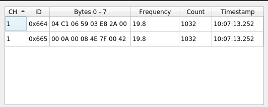
All operations on CAN inputs, such as creating new, editing, deleting, import, export, are available from context menu. There is also CAN Monitor tool available to see all CAN frames being received on the bus.
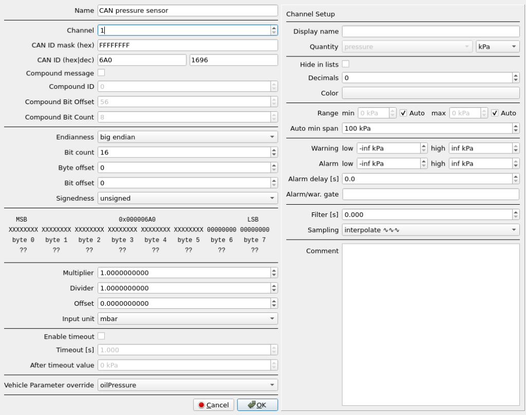
- Name – user assigned CAN Input name.
- Channel – interface CAN bus channel ID. The dyno controller is equipped with two physical CAN buses.
- CAN ID mask – masks the part of the message ID to be compared with the configured CAN ID. Can be used if the CAN ID contains some part that is variable, like for example sender ECU number. Data is parsed for the channel if channel CAN ID == (CAN frame ID & CAN ID mask)
- CAN ID – CAN message ID
- Compound message – option to parse the message as compound type. This format is based on sending multiple information with the same CAN message ID with an extra identifying number in some part of the message data.
- Compound ID – number that must be matched in the message data
- Compound Bit Offset – offset position of the compound ID
- Compound Bit Count – number of bits to get for the compound ID
- Endianness – Byte order in the CAN message. Big Endian is the most common format. In this format, the most significant byte is sent first (byte 0). It is possible to decode CAN message in Little Endian format. In Little Endian byte order is reversed and byte 0 is the least significant.
- Bit count – Number of bits to extract from the CAN message.
- Byte offset, Bit offset – Position in the message to start data extraction. The offset is always counted from the right side, from the least significant bit, after taking the endianness into account. Position = Byte offset * 8 + Bit offset.
- Signedness – Defines if extracted number will be interpreted as unsigned or signed. A signed number is a number that can have negative values. Two’s complement format is used for signed numbers.
Next window area shows preview of the data extraction. The most significant byte is always placed on the left side.
Next line shows byte numbering same with CAN bus byte numbering. Byte 0 is the one that is sent first. Byte numbering labels are changed according to the selected Endianness.
Next line shows message bits which will be extracted according to Bit count, Byte offset and Bit offset. X characters mark the bits that are not extracted. If the line is highlighted in red, it means that the required bit count can’t be extracted at the set position.
Next line shows live preview of data being received on entered CAN channel with matching ID.
- Multiplier – extracted number multiplier
- Divider – extracted number divider
- Offset – constant added to the extracted number
- Input unit – unit used to convert input data to SI units used internally by all channels – input unit choice is available after selecting channel quantity (1).
CAN Input value = Unit_Conversion (extracted number * Multiplier / Divider + Offset)
- Enable timeout – Enables the timeout function that overwrites CAN Input value when the required CAN message is not received.
- Timeout – Time required to pass, to override CAN Input value.
- After timeout value – The value that will be set in the absence of required CAN message.
- Vehicle Parameter override – Can be selected to override a Vehicle Parameter channel that is built in the software. This way, you can have one widget configured that displays VP_oilPressure, but it will take data from any CAN channel that gets the data at that time.
When setting up a new CAN input channel, it’s important to select the correct Quantity and Input unit. This will allow the software to hold the value in SI units and convert it to any preferred unit when displaying it to the user.
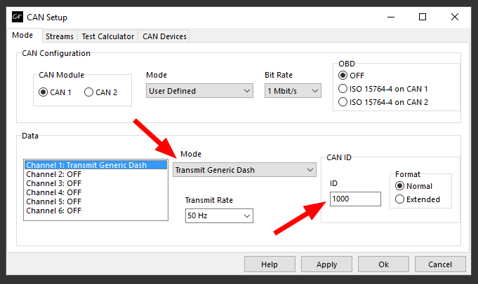
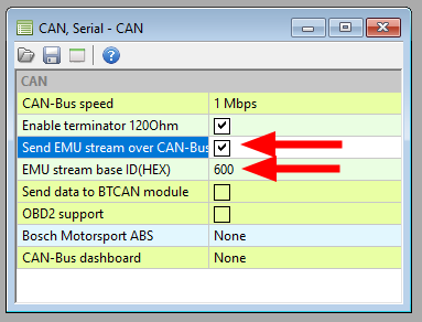
How to enable CAN data stream compatible with premade dyno configuration?
Ecumaster
Link ECU