Tire slip is a phenomenon that most of you will encounter sooner on later on your dyno. I’m writing this article to make you aware of the effects of slip on the dyno and ways to deal with it.
Tire mechanics basics
I hope that you know that you can’t exert force without deformation. In simple case, if you’re pushing something with your finger, the finger deforms the harder you push. No deformation occurs only if you’re not pushing. The same is true with a tire. A tire that is transferring force to a roller is deforming (and slipping when in rotation) in a relation to the transferred force. With bigger force, comes bigger deformation and slip.
You may say that you don’t want any tire slip on the dyno, because it messes up tires and measurement. Unfortunately, zero slip is not possible in tire – roller arrangement. You have to live with just a bit of it.
Let’s go now through some illustrations from Michelin that will help you to visualize what’s going on with the tire.

When the tire transfers force to the road (or roller in our case), at a part of the contact patch the rubber adheres to the roller surface and in the rest of the patch it starts slipping. Let’s reformulate our desire about lack of slipping on the dyno. We don’t want the “slippage phase” to be as wide as the whole contact patch, because in that case the tire surface will start moving much faster than the roller surface. This will just generate lots of smoke and lack of power on the dyno chart. We want to operate in conditions where we still have some width of the shear phase. Let’s take a look at this with a more abstract model of tire friction.
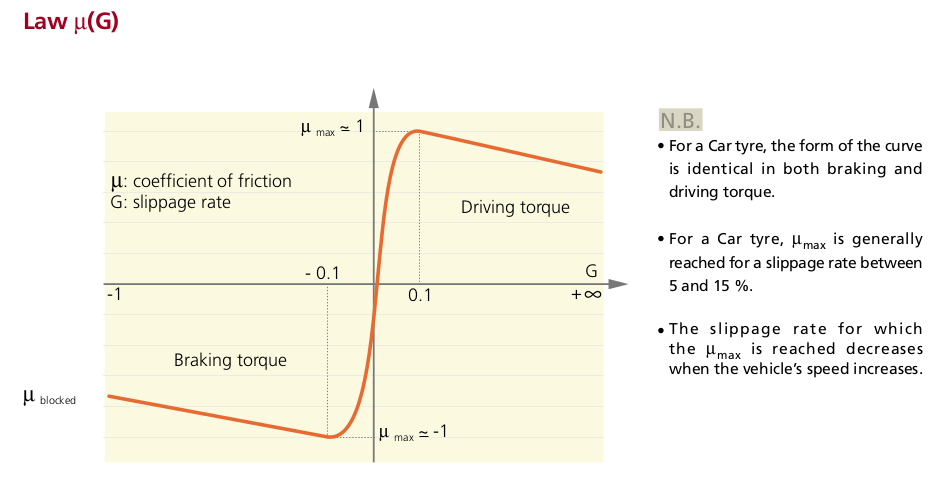
Up to some slip value (5% – 15% depending on tire and roller construction), we will approach the maximum coefficient of friction between tire and roller. That’s the area acceptable for us. Beyond that, there’s only smoke and frustration.
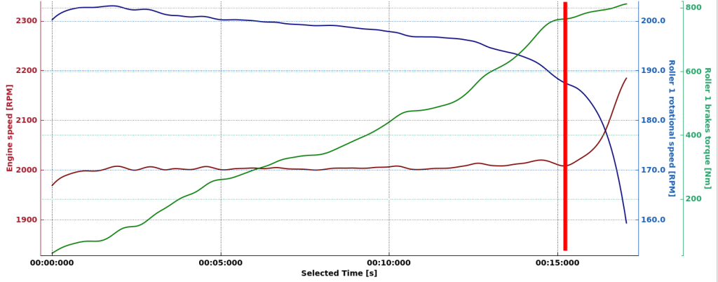
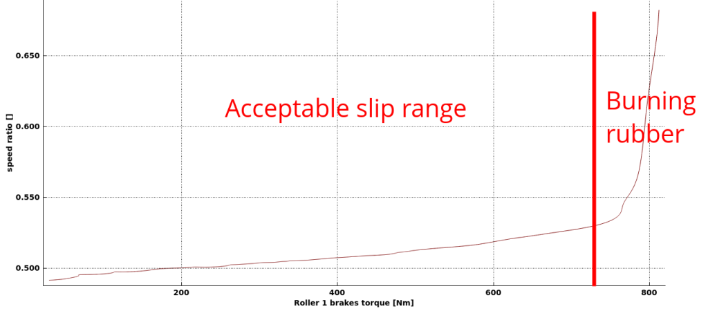
Below is one of my tests from driving on the rollers in low gear and pressing on the throttle more and more. Up to some amount of transferred torque, the slip value increases, but nothing drastic happens. At some point the tire loses grip and that’s the point that we don’t want to cross while doing measurements. Below that, the slip is acceptable and unavoidable.
Slip effects on roller dyno
Let’s get to the point of this article. The aspect of tire slip that I want to focus on here is that even in our acceptable slip operation range, the tire speed in relation to roller speed changes with the amount of power that is transferred.
Engine – roller speed ratio aspect
When transferring power, the tire to roller speed ratio will be higher than when idling. This obviously causes some trouble if we calculate engine speed from roller speed with a constant ratio.
We usually calibrate the engine – roller speed ratio when idling. There is only a minimal power transfer when idling. Later, the measurement is made at full throttle. This in reality changes the real speed ratio and has influence on the results. Here is an example: I have two runs made one after other on the same car where I have real engine speed readout via CAN bus. The engine – roller speed ratio was calibrated when idling and gave a result of 2.424. Under load, the speed ratio changed to 2.468. That is roughly 2% slip. It’s not a powerful car. Only 180PS. The effect will be bigger with more powerful cars. That’s the effect of changed speed ratio on the result:
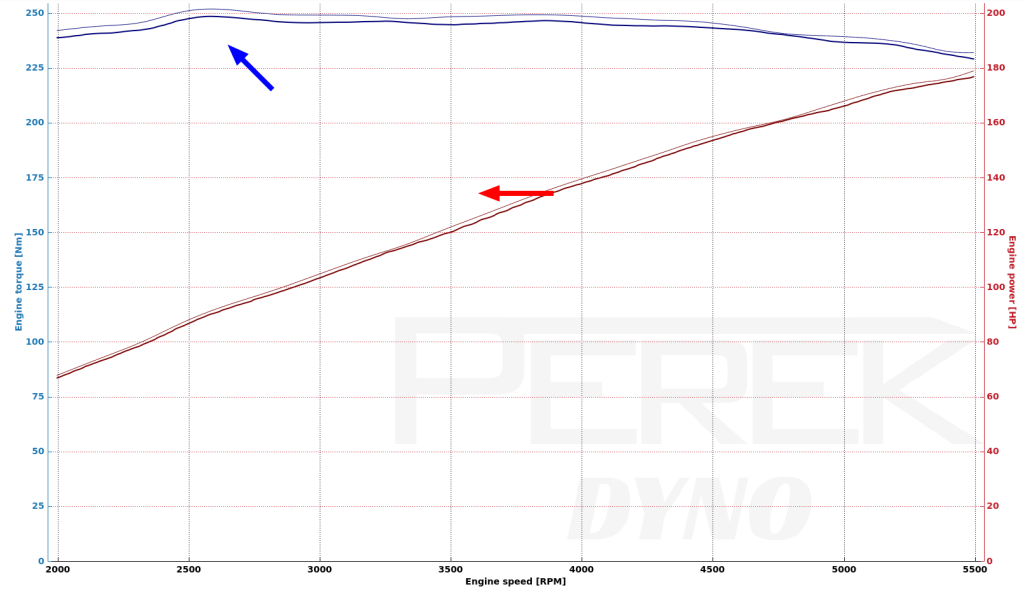
Thicker line is the true measurement, with engine speed sourced from CAN bus. Thin line is the one with speed ratio calibrated when idling. A calculation, done with lower-than-real speed ratio, moves the power curve to the left and the torque curve to the left and toward higher values. The effect is not really dramatic in this example, but I want you to know that this exists and that it will be bigger when we get to higher slip values.
What to do about this issue? You’re in luck if you have separate measurement of engine speed like CAN bus stream from aftermarket ECU, OBD or inductive clamp. In that case, you’re covered. If you need to use calculated speed ratio on absorber dyno, you can switch the brake control to speed control mode and calibrate the speed ratio under load.
Another issue with changing speed ratio is tuning the car in steady state. If you’re doing this with calculated speed ratio, then you will be always a bit off from the desired engine speed, depending on the amount of power transferred from tire to roller. Fortunately, if you have feedback on the engine speed, the changing ratio is automatically compensated in the controller.
Power measurement aspect on two rollers per axle absorber dyno
I want to give this issue a separate section, because it’s a big one on a particular configuration of dyno rollers, absorber and speed sensor. Let’s analyze operation of this dynamometer:
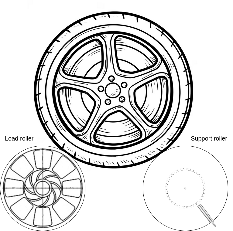
I hope that after reading the previous part of this article, you are already suspecting what the problem might be. The dyno has two rollers per axle. Rollers are not linked. Absorber is placed on the front roller, which we will call “load roller”. The speed sensor is placed on the rear “support roller”. When we are idling, nothing bad is happening. What happens in steady state? The wheel is transferring nearly the whole engine power to the front roller and the absorber. Let’s say this causes 5% slip between wheel and front roller. Nearly none of the power is transferred to the support roller, so let’s assume there is no slip there. Now, the support roller where we measure roller speed rotates 5% faster than the load roller. To calculate the power, we must multiply absorber torque by its rotational speed. Do we use the support roller speed? That directly creates 5% error in power calculation. Don’t get me started on the effects of placing a rubber tire in the PID control loop of absorber speed… In short: It forces you to settle on much slower and less precise speed control.
So if you have a dyno with this construction, please just move the sensor to the load roller. Or better add another sensor on the load roller.
Slip measurement and compensation with two sensors per axle
Let’s now review the next dyno design with two speed sensors.
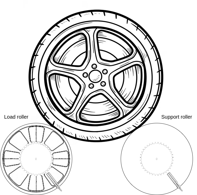
This dyno design has a speed sensor installed both on the load roller and support roller. This gives us a perfect calculation of power received by the absorber and load roller. A separate sensor on the support roller also gives us independent calculation of power received by the support roller. We’re covered on power calculation. Now what about the engine speed calculation from constant speed ratio? We also have that covered. We use the support roller for that. If we make the support roller lighter, or if we load the front roller with absorber, then most of the power goes to the front roller and a smaller part to the rear one. This gives us less or none slip on the support roller and reduces its effect on engine speed calculation. Moreover, the information about support roller speed can be used to calculate new load roller target speed, which in turn gives us corrected engine speed match in steady state tuning. The good stuff doesn’t end here. If we try to put more power on the dyno than the tire grip can handle, then we will clearly see the support roller rotating faster than the load roller before we smell the burned rubber. One more sensor, four advantages! Time to set it up in the software.
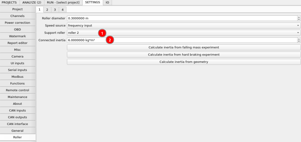
We will use input number 1 for the load roller. We set the corresponding support roller for it to “roller 2”. This enables engine speed calculation correction and load roller target speed correction. In the connected inertia, we only enter the moment of inertia associated with the load roller.
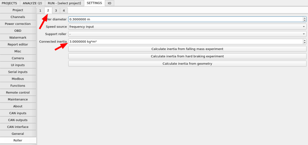
Our support roller will be connected to input number two. Here we enter the moment of inertia associated only with the support roller.
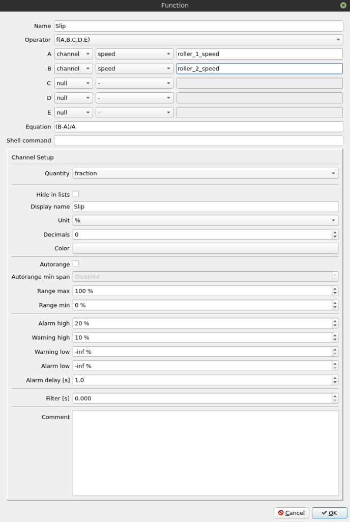
The slip calculation function gives us two important features. One is the warning set at 10%. If we have a widget displaying the slip value placed on the desktop, it will be highlighted in yellow when we get more than 10% slip, which is quite a lot. Another feature is the alarm set at 20%. If we have 20% slip or more, then we are surely already burning rubber and the alarm in the status bar will let us know to immediately lift the throttle. Of course, you can do your own experimenting and adjust the warning and alarm threshold according to your preferences.
Slip measurement on dyno with one speed sensor per axle
If we have single-roller dyno or double roller dyno with linked rollers or just we don’t want to install a separate sensor on the support roller, then the slip measurement and detection is not that straight forward.
First, let’s work on the answer to the big question: Did the car slip during the measurement? I have a drop in the power and torque curve. Is it the car slipping?
On the absorber dyno, that has adequately sized absorber, it’s quite easy to get a clue about it. If you’re worried you had slip at 3000 RPM then set the speed control to 3000 RPM and go full throttle. If the dyno holds the speed or if the speed is held just a few percent over the target, then you don’t have a slip problem. If the engine goes to rev limiter or just more than 20% above target, and you smell burning rubber, then it’s highly probable that during the run your drop in power may be caused by excessive slip.
What about slip measurement? That’s a bit more tricky. You will need some information about engine speed. This can be a CAN bus stream from an aftermarket ECU, additional engine speed sensor or OBD data connection.
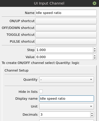
We need to add input channel to save a reference speed ratio:
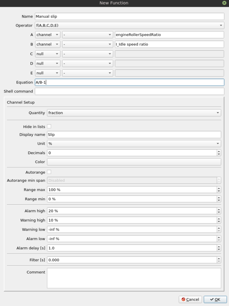
Then a function to calculate slip from saved speed ratio and current one:
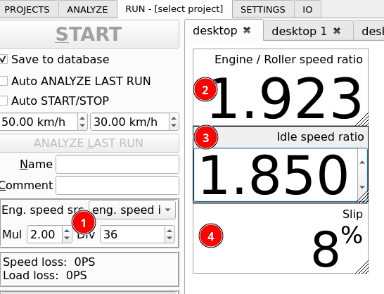
Now, when we start working on a vehicle, we need to set up the engine speed source to the one that we have available (1). Then we drive at some speed on low throttle and copy the calculated speed ratio (2) to our input channel (3). With this setup, when we go full throttle the slip will create a higher calculated speed ratio which together with our manually entered reference idle speed ratio will be used to calculate the slip value.
Slip estimation
If we don’t have any ways of measuring slip, like the support roller or additional engine speed signal, then we can estimate slip and correct engine speed calculation using the measured tractive force.
The algorithm is based on the model of tire friction mentioned earlier. In low slip values, the slip is roughly proportional to the driving torque (or the tractive force). The equation used for estimation is:
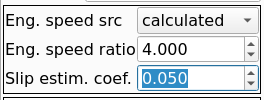
slip = (tractive force / vehicle weight on driving wheels) * slip estimation coefficient
Basically the slip estimation coefficient tells the dyno software what the slip will be at the used friction coefficient equal to 1.0. The estimation coefficient will depend on the roller surface finish and tires. You can expect values from 0.03 to 0.15.
To tune the coefficient, you need to drive in the constant speed absorber mode, and tune it, so no matter if you’re driving on little throttle or full throttle, the real engine speed stays the same. If after pressing the throttle the engine speed stays higher, increase the coefficient. If it goes lower than on partial throttle, then the coefficient is too high.
Reducing the slip
We already know our enemy well. Here are some ways to fight the rubber – burning slip values:
- Use tire glue / spray on show chain.
- Add a hook directly under the axle that will allow you to pull the vehicle down with straps to press it more to the roller. Alternatively, just put some weights inside or ask your friends to sit in the car.
- Modify unlinked roller setup to linked roller setup.