Roller speed measurement is implemented with use of a sensor connected to controller Frequency input.
Requirements for sensor signal:
- Maximum voltage: 15V.
- Signal must pass through a 2.5V level with 1.2V hysteresis. Putting this requirement in other words: low state must be lower than 1.9V and high above 3.1V.
- Signal frequency at top roller speed must not exceed maximum allowable frequency 15kHz. Supplying signal of higher frequency will result in faulty measurement results.
- For high-precision signal, a sensor with fast falling signal edge is suggested. An example sensor satisfying this requirement is a Hall type sensor.
PEREK offers general purpose HS3 hall sensor that satisfies signal requirements.
With the introduction of new DC1E4 controller, there are two paths to follow to get speed signal:
Pulse capture mode
In this mode the controller measures time between subsequent signals received on the frequency input with 31.25ns resolution. This mode is usable from 15mHz-15kHz. The measurement precision in this mode reduces with higher rotational speeds from 0.0032% @ 1kHz to 0.045% @ 15kHz, which is excellent. Higher frequencies will further reduce the precision, however the measurement method in MCU restricts higher frequency readout. The dyno control quality in this mode depends mostly on toothed wheel precision and sensor quality.
Tooth count should be selected such it will not produce signal frequency higher than 15kHz on maximum dyno speed and produce at least 100Hz signal at lowest speed you want to use brake control. Lower frequencies are also possible, but may cause lower than peak brake control performance. For most dynos, the ballpark is around 36 signals per rotation.
Pulse count mode
Pulse count mode is introduced with new DC1E4 controller in response to request for high signal count encoders. This mode samples frequency 1000 times per second, and it is usable with signal from 10kHz to 10Mhz. Contrary to pulse capture mode, here the speed measurement precision increases with frequency:
Pulse count mode precision [%] = 1000Hz / Input frequency * 100%
For example 100kHz signal will give 1% precise measurement every 1ms. This may seem poor, but the subsequent samples are filtered and result in measurement accuracy equal to system clock, which is 0.003%
At frequencies lower than 10kHz, the speed readout will still be available, but it will lose precision so much that in won’t be usable for brake control. A single pulse will manifest as 1 sample of 1000Hz signal.
Signal count should be selected such it will not produce signal frequency higher than 10Mhz on maximum dyno speed and produce at least 10kHz signal at lowest speed you want to use brake control. For most dynos, the ballpark is around 2500 signals per rotation. Keep in mind that most encoders can produce signal up to 300kHz.
Selecting right amount of signals per roller rotation
First, you have to decide, if you want to use a toothed wheel or encoder. It depends mostly on which is easier to install in your dyno. If done properly, both devices will give your dyno accuracy so high, that it’s effect on measurement result will be negligible. Encoders are a bit more expensive than the toothed wheel with hall sensor solution.
The calculator below will help you to check if your selection will perform well.
Dyno speed
km/h
Roller diameter
mm
Signals per rotation
Signal frequency
Hz
Speed signal quality
Speed signal must be uniform. Getting signal from toothed wheel with missing teeth is not allowed. Engine speed input is an exception from that requirement. It could have signal from a wheel with missing teeth, for example a typical 60-2 wheel is accepted.
In case of inertial dyno it’s very important for the consecutive speed pulses to be emitted with equal time spacing. If the next signal delay would be shorter than the last, for the dyno controller it constitutes to roller acceleration, what in turn is calculated as a power measurement. Fundamental dyno equation plays the role here:
Power = rotational speed * rotational acceleration * inertia
Signal delay variation below 1% is a value to aim for. Signal with variation higher than 5% may require strong filtering.
The dyno software is equipped with a tool to analyze roller speed signal quality. To access the tool, right-click on the measurement loaded in ANALYZE tab, and select Analyze Speed Signal.
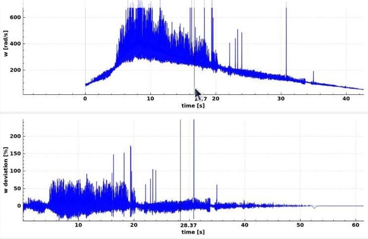
An example of a faulty speed signal is presented below. Presence of speed deviations higher than 50% suggest noise in the speed signal.
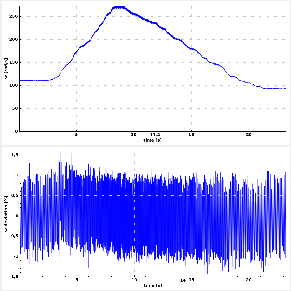
Presented below is an acceptable speed signal. Deviation from average is around 1%.
Toothed wheel for the speed sensor
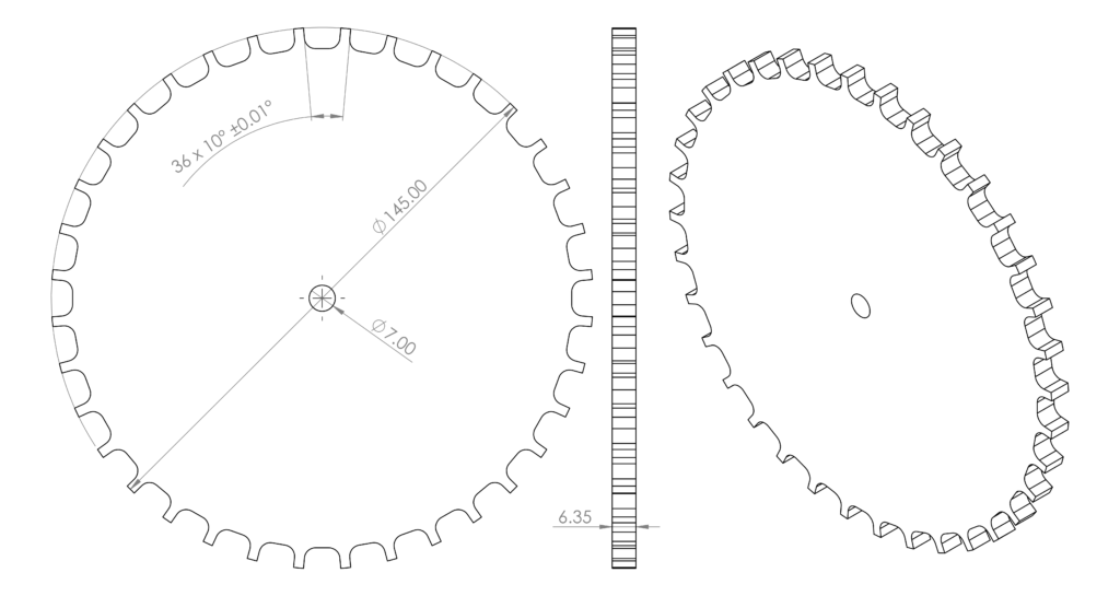
Higher tooth count will result in better absorption dyno brake control. Frequency generated with the wheel, while the roller rotates in operating range, must be in 2Hz to 15kHz range. Machining the wheel, with the best achievable precision, minimizes measurement noise. It’s advised to machine the wheel with a machine equipped with indexing head or table. Cutting the wheel with laser, water jet or general purpose mill is not advised. The wheel must be made from ferromagnetic material. Cold-rolled steel is suggested. The wheel can’t be made from stainless steel or aluminum. The wheel can be protected from rust by plating with zinc or nickel. Painting is not advised.
Precision made, zinc plated wheels dedicated for HS3 sensor could be bought from PEREK.
Example 14.5cm, 36 teeth wheel design is presented below: