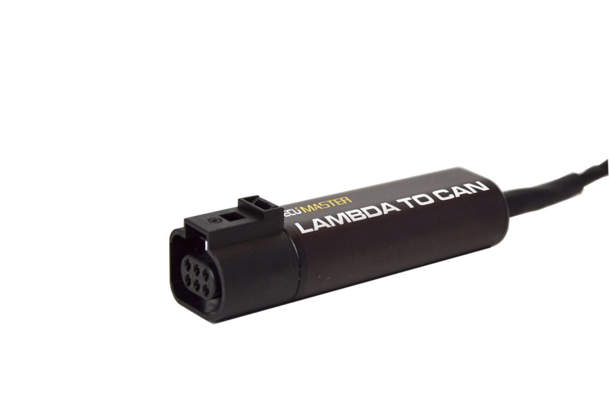
DC series dyno controller is compatible with Ecumaster Lambda to CAN wideband oxygen sensor controller.
To achieve maximum accuracy, the Lambda controller should be connected to DC series controller via CAN bus.
One controller with sensor connected uses around 1.5A peak current and can be supplied from 12V output built in DC1/DC1E4/DC2 if no other receivers with significant power requirement are connected to the supply. If more controllers are required, external power supply should be used.
| DC Series Dyno Controller | Additional 12V power supply | Lambda to CAN 1 | Lambda to CAN n |
| GND | GND | GND | GND |
| +12V | V+ | V+ | |
| CAN 1 H | CAN high | CAN high | |
| CAN 1 L | CAN low | CAN low |
The CAN bus connection should be made with twisted pair wires, and it should be terminated on both ends with 120Ohm resistors. On the DC series controller side, the bus can be terminated with build in software controlled resistor.

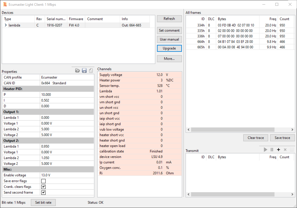
Lambda to CAN default configuration enables the controller when the engine is running by monitoring power supply voltage. To use the controller with 12V power supply, “Enable voltage” should be lowered to 9V. The devices purchased from my shop are already reconfigured to work correctly with 12V supply and 1Mbit CAN bus bitrate.
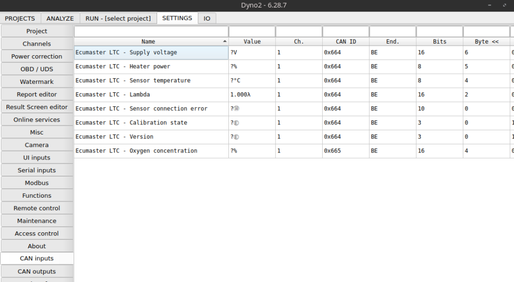
When using multiple controllers, each controller must have different “CAN ID” associated. The controller can send frames on two following IDs, so the IDs should be spaced by at least 2. For example: controller 1 CAN ID: 0x664, controller 2 CAN ID: 0x666, controller 3 CAN ID: 0x668. Note the “Bit rate” setting, as it needs to be the same in the dyno controller setting.
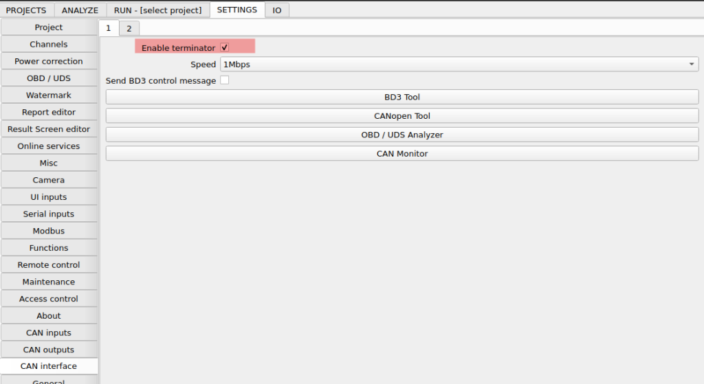
On the dyno controller side the terminating resistor can be enabled in CAN interface settings.
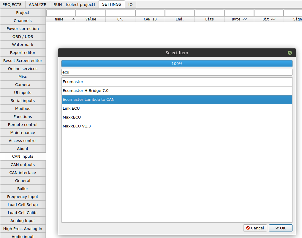
If the controller is connected to the Internet, the CAN input channels can be quickly imported from server from right-click menu on CAN Input channel list > Import form server