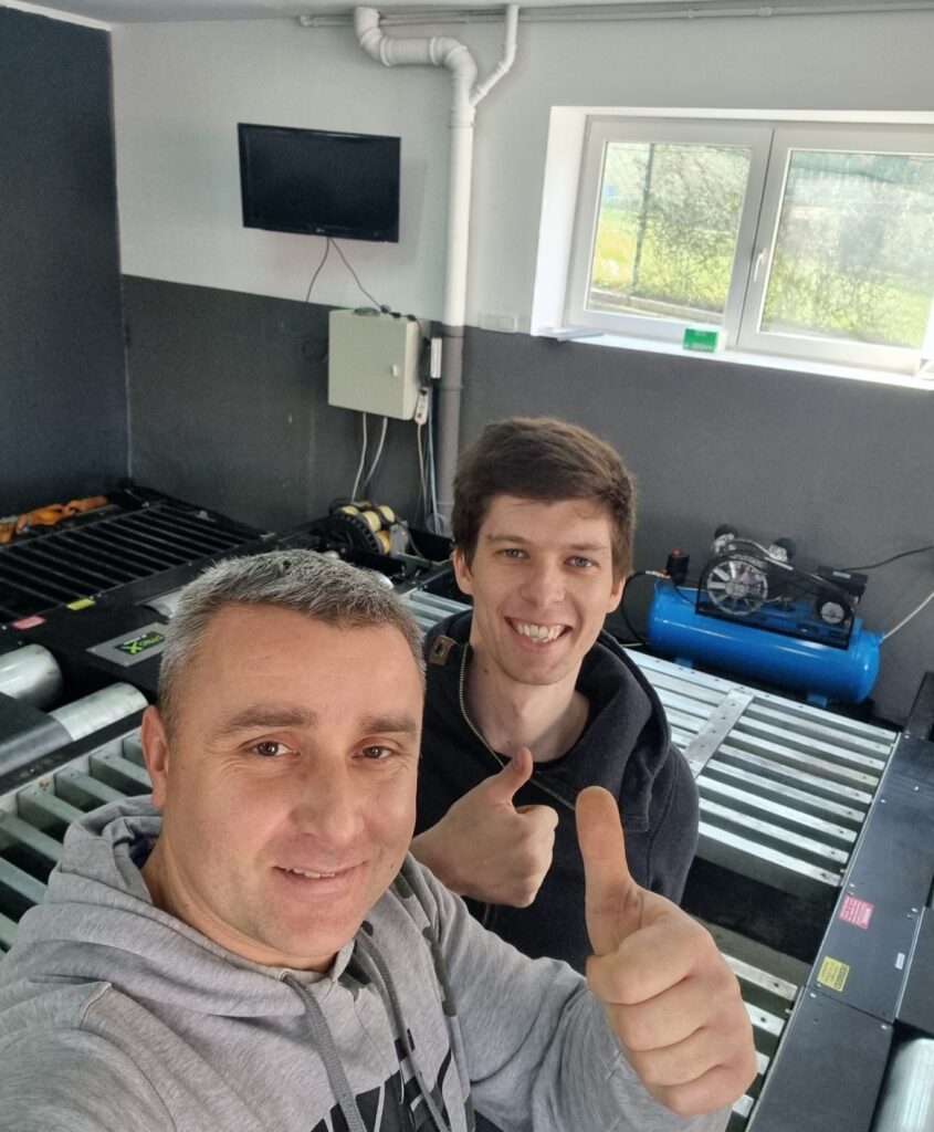
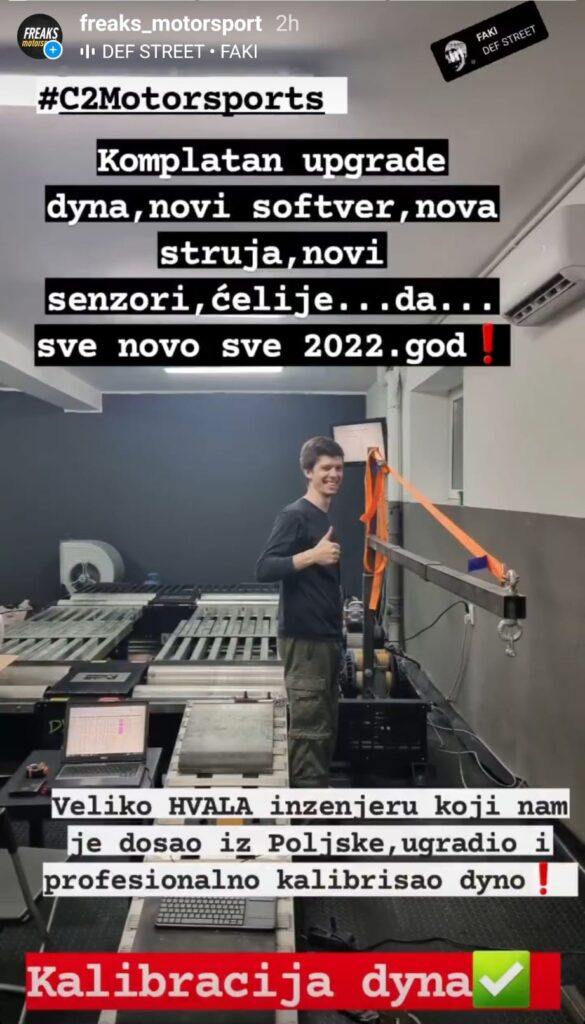
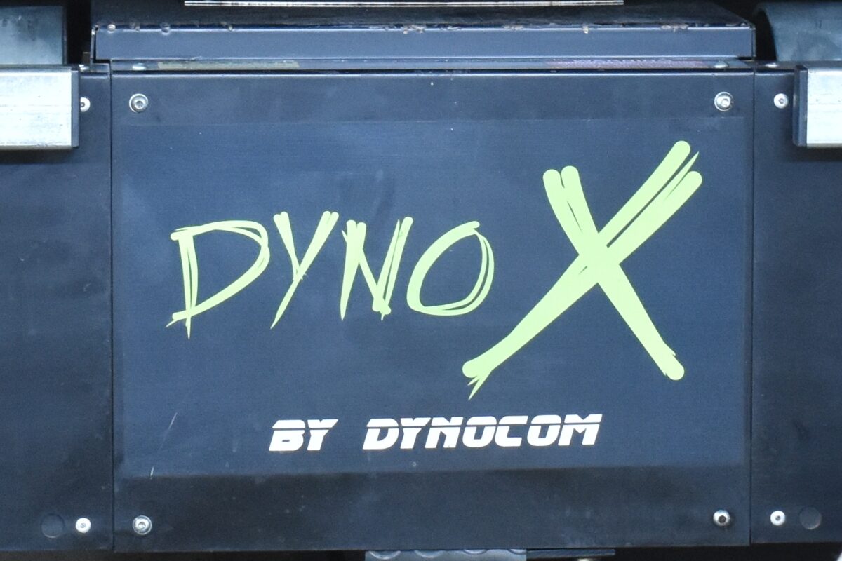
This November, I visited Freaks Motorsport tuning company in Belgrade, Serbia. The task was to make wiring, setup and calibration to run AWD Dynocom DYNO X dyno on PEREK controller.
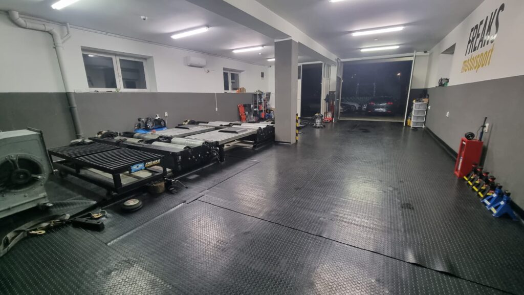
We decided to replace the speed sensors and load cells. The owner received the package from me, so he could manufacture all required mechanical adaptations before I arrive.
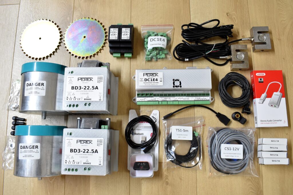
The parts required for this conversion were:
- DC1E4 dyno controller
- 2x BD3-22.5A-600uF eddy brake power supplies with fast demagnetization
- 2x S-type 500kg load cells with LCA1 amplifiers and rod ends
- 2x signal wheels and speed sensors
When I arrived, the speed sensor and signal wheel were already in place and ready for wiring.
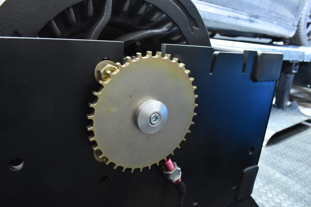
On the first day, I made wiring for the dyno, and we calibrated the load cells.
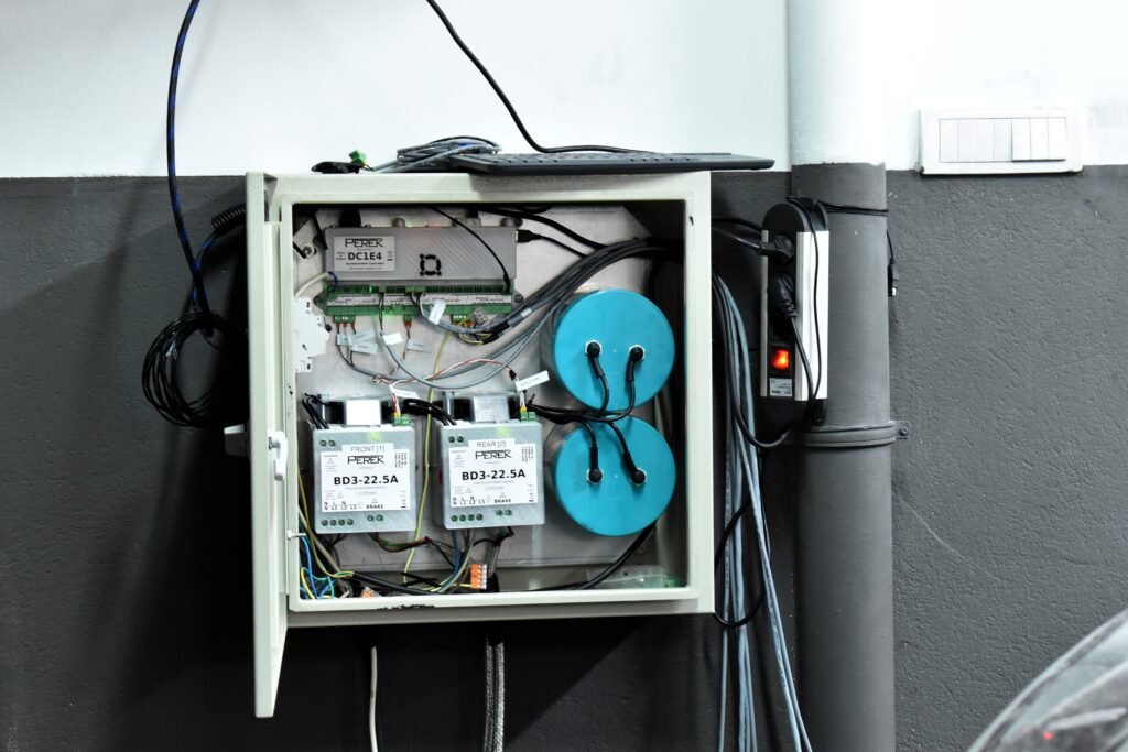
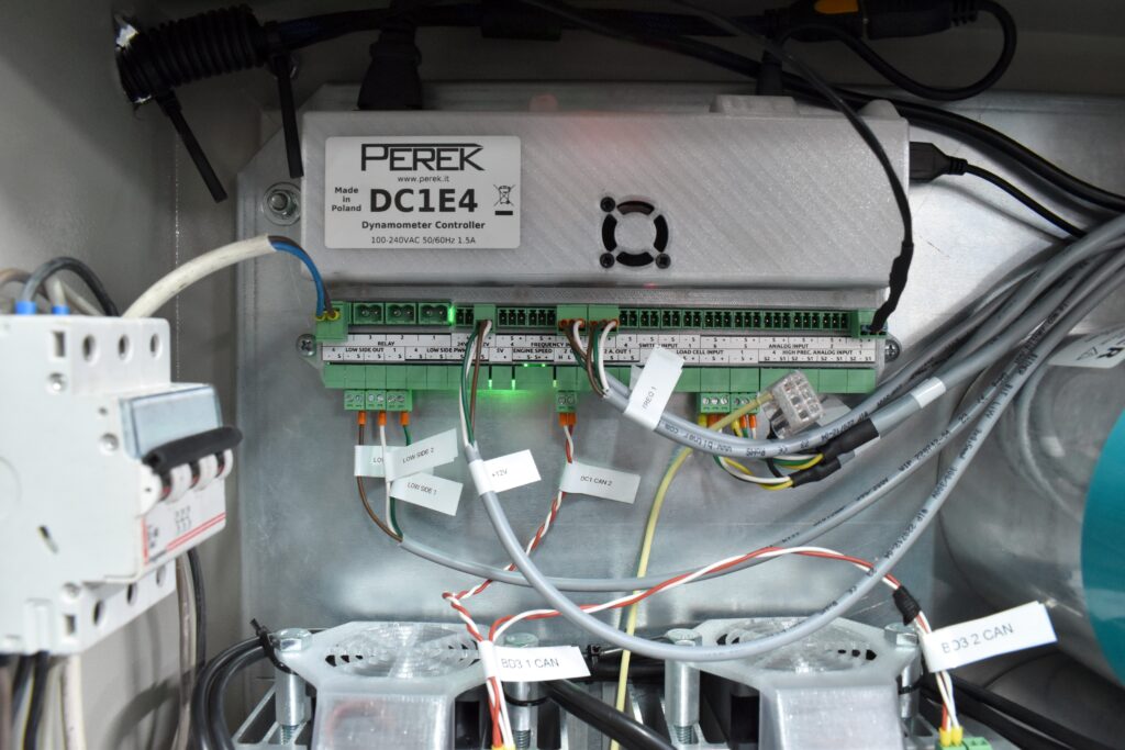
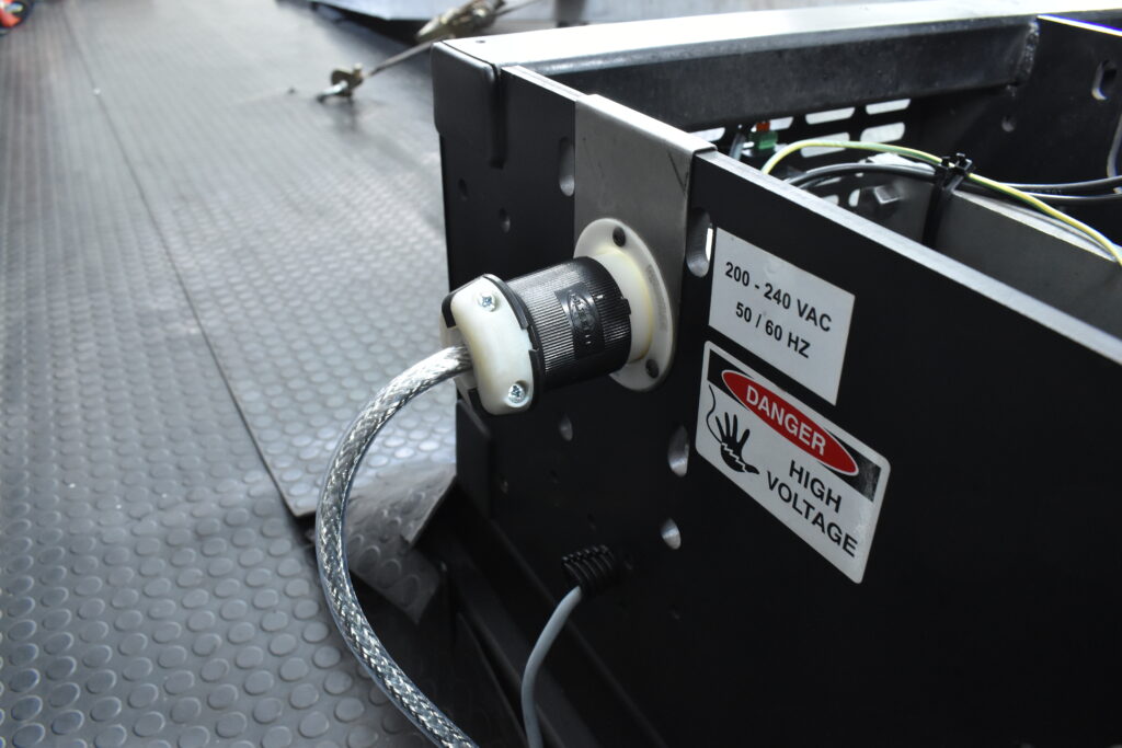
Dynocom had a nice eddy brake connector, which we reused for new wiring.
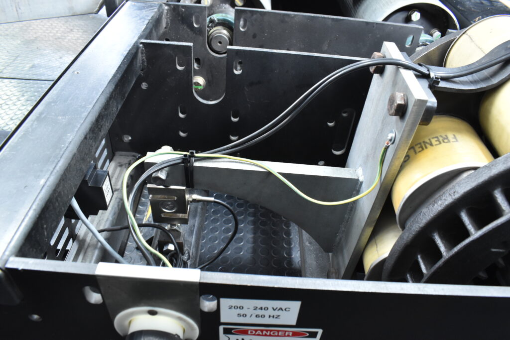
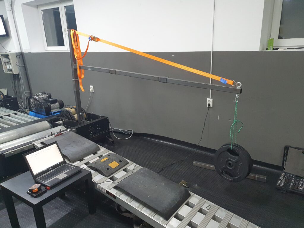
The dyno is equipped with two Frenelsa F16-125 eddy current brakes. We calibrated the load cell for it with 59kg on 2.75m long arm which gives 1600Nm calibration torque.
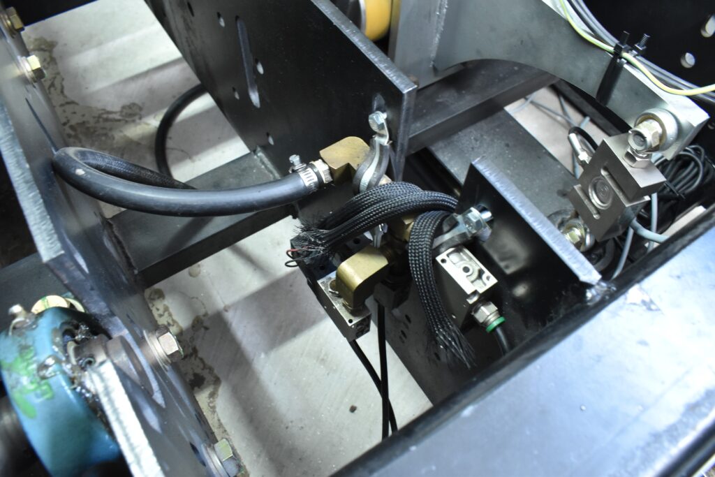
The next day, we tested automatic dyno fan control and wheelbase regulation to the dyno. Dynocom wheelbase is regulated with a pneumatic actuator that is controlled with three small valves. The valves use so little current that these can be powered and controlled directly from DC1 dyno controller without an external power supply.
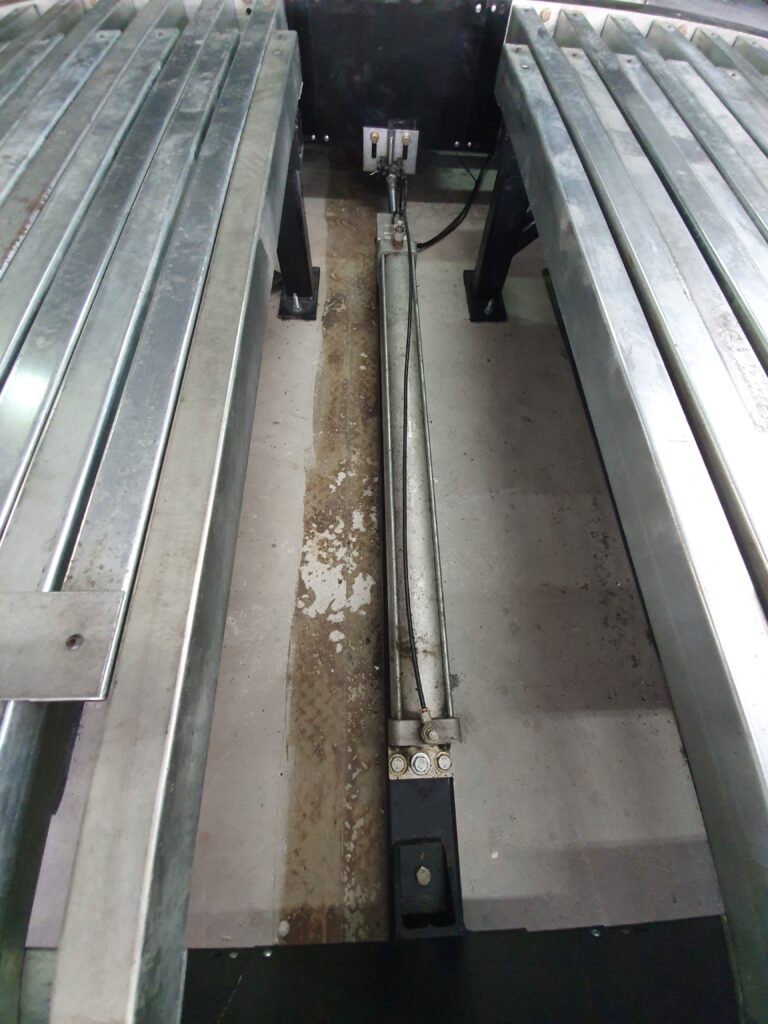
After we had the wheelbase and fan under our control, I started tuning eddy brake PID controllers with my Toyota tuning tool 😉
After PID tuning, I measured the dyno moment of inertia to be sure that the software compensates for it correctly. Double ramp calibration method pointed to the value of 2.6kgm².
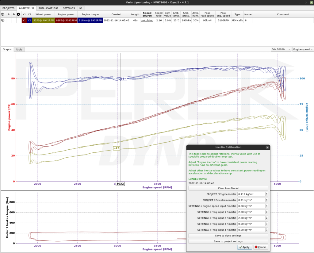
At this moment, the dyno was fully tuned and calibrated, and the time came to instruct the owner how to use it and to test how well the Dynocom hardware can cope with a more powerful car.
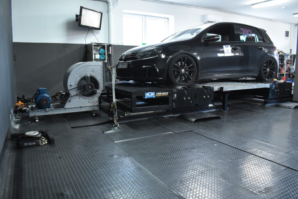
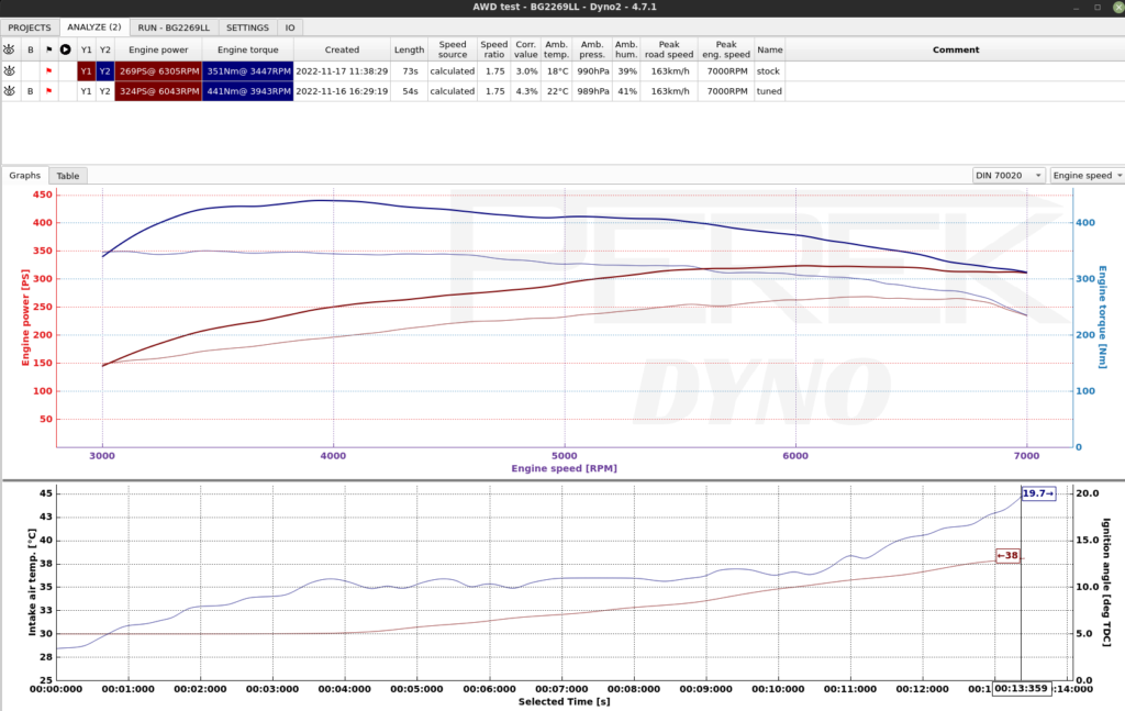
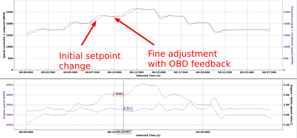
Using OBD feedback in steady state mode allows compensating for engine-roller speed ratio change due to changing tire load and vehicle position on the roller. This mode will keep your engine speed at a precisely set value, even on chassis dyno.
After all final checks and tests were done. What I left in Belgrade was a well functioning dyno and a happy customer!
