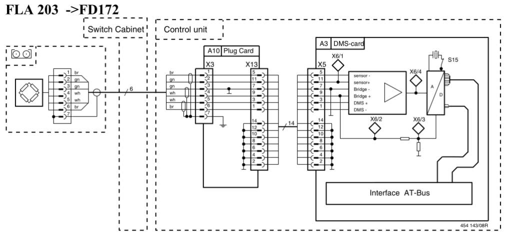
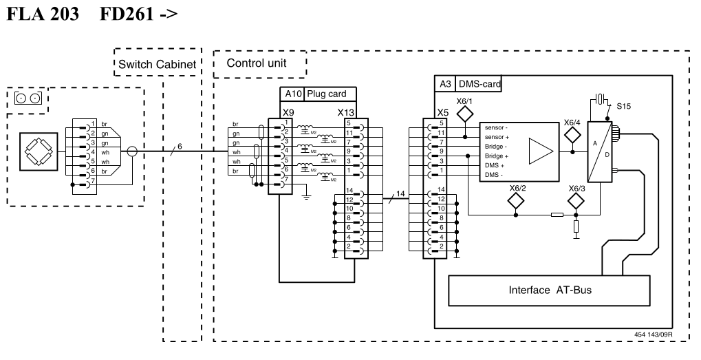
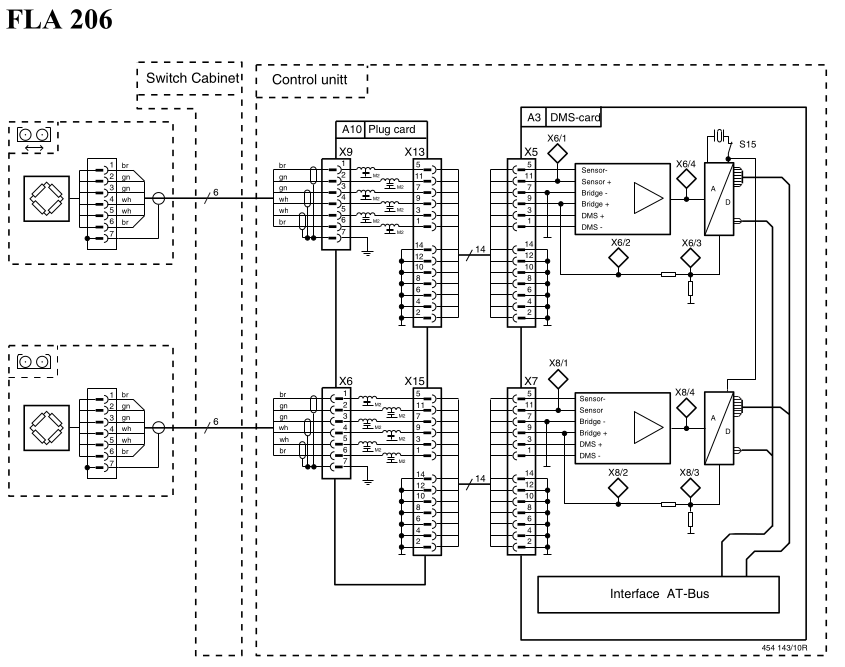
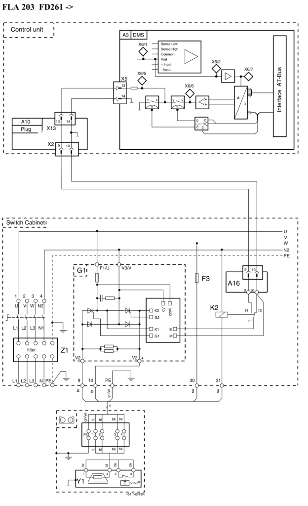
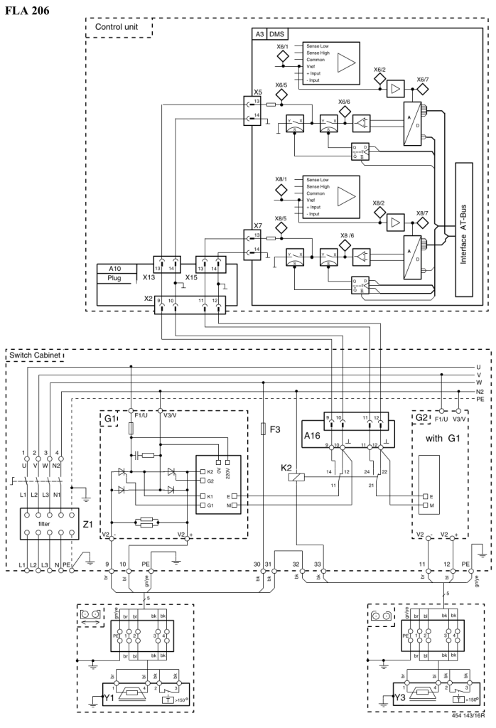
The Bosch FLA 206 (4WD) and Bosch FLA 203 (2WD) chassis dynamometers are a series of double roller, non-linked high quality dynamometers from Bosch. They are equipped with 1600Nm Frenelsa eddy brake per axle, pneumatic lift and hydraulic wheelbase adjustment. Suggested dyno controller upgrade for Bosch FLA 206 and Bosch FLA 203 is PEREK DC2.
Speed sensors
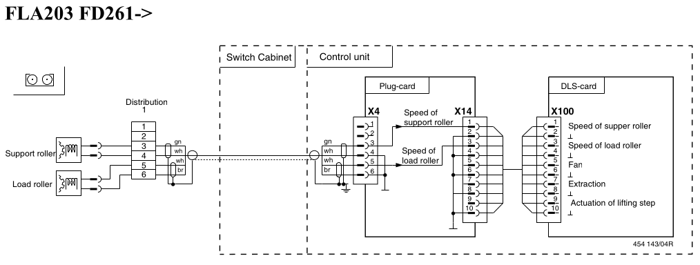
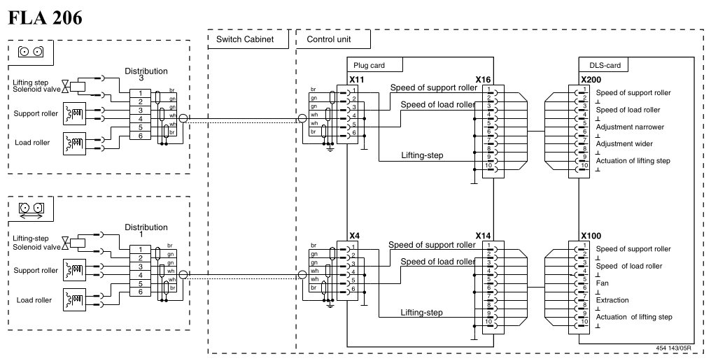
The dyno uses one speed sensor per each roller. The ability to separately measure speed of the load roller and of the support roller allows detecting slip. Bosch FLA 203 has 2 speed sensors and Bosch FLA 206 has 4 speed sensors. The speed sensors are VR type with 100 signal per rotation trigger wheels. Nominal gap to the signal wheel is 0.1mm-0.3mm
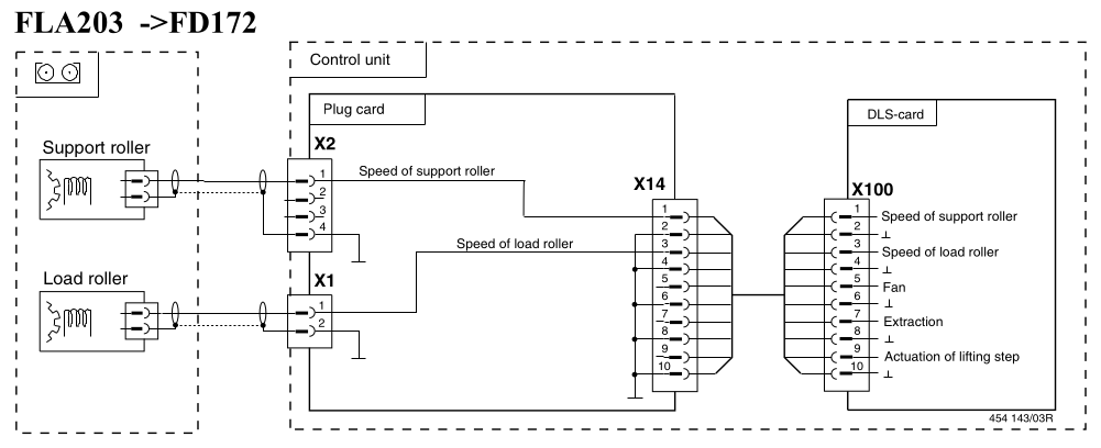
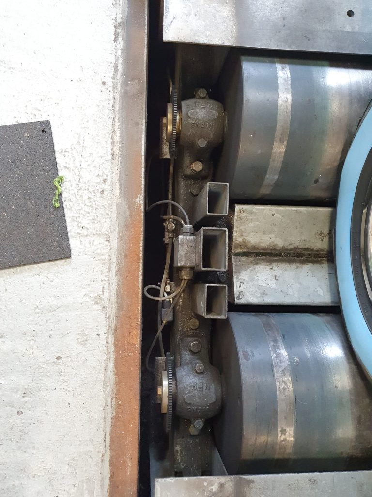
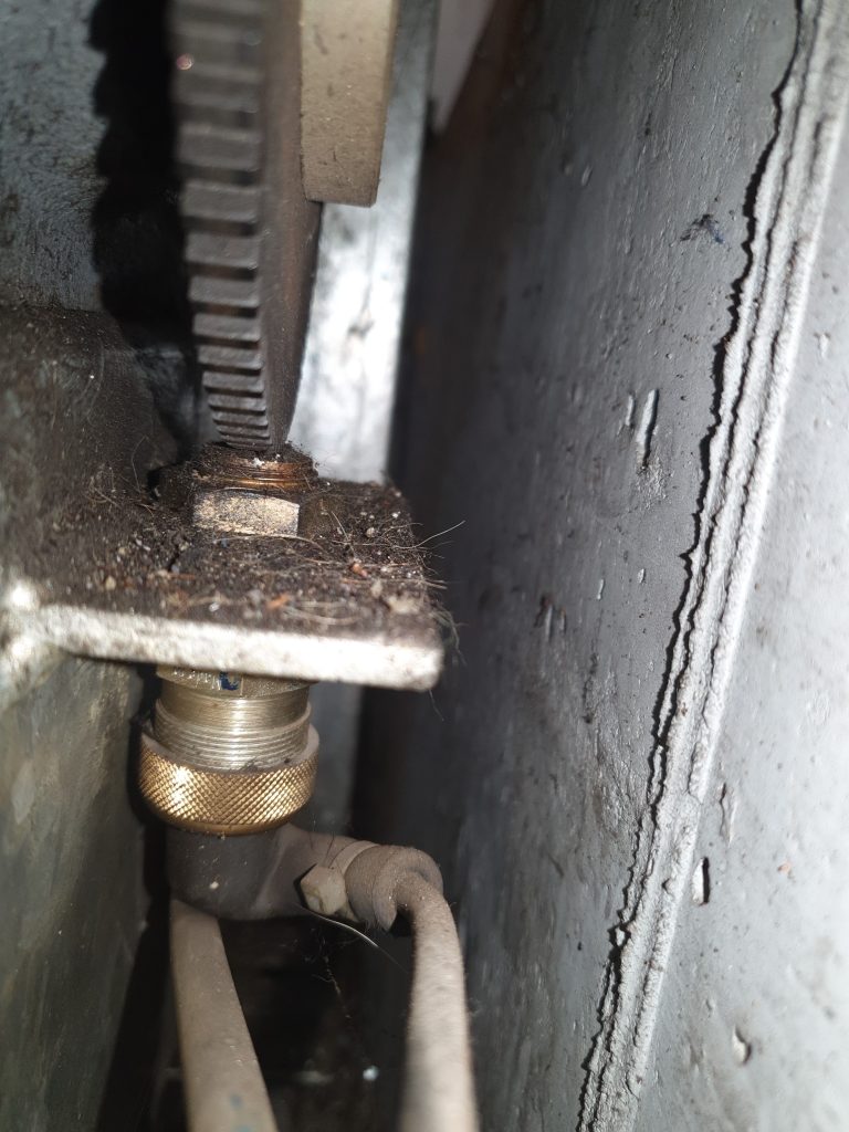
To reuse the VR type speed sensors, it is required to connect them via a VRI2 adapters. To avoid getting noise on the speed signal, the VRI2 adapters need to be adjusted to drop the speed signal below 3km/h. The polarity of the sensors is not important.
Suggested connection:
Frequency input 1 – Load roller 1
Frequency input 2 – Support roller 1
Frequency input 3 – Load roller 2
Frequency input 4 – Support roller 2
If the stock sensor is damaged or missing, it can be replaced with a HS3 speed sensor and a new signal wheel (the stock one has too small teeth for HS3). In case of replacing the sensor, the VRI2 adapter is not needed.
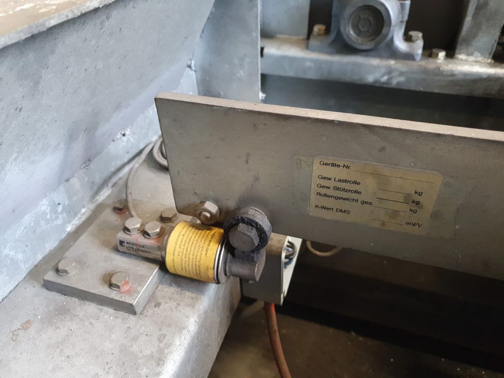
Load cell (torque sensor)
The load cell installed on Bosch FLA 206 is beam type. The connection with torque arm allows it to measure torque only in one roller rotation direction. If bidirectional operation of the dyno is needed, it’s suggested to replace it with an S-type load cell connected to the torque arm and base with rod ends.
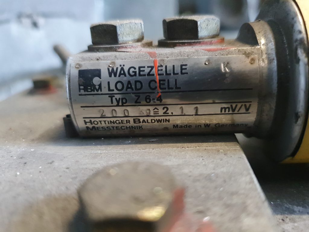
Stock load cell wiring pinout:
| brown – green pair | brown | EXC+ |
| brown – green pair | green | EXC- |
| green – white pair | green | EXC + |
| green – white pair | white | EXC – |
| white – brown pair | white | SIG+ |
| white – brown pair | brown | SIG- |
| all shields | all shields | SHLD |
Suggested connection:
Load cell input 1 – Load cell 1
Load cell input 3 – Load cell 2
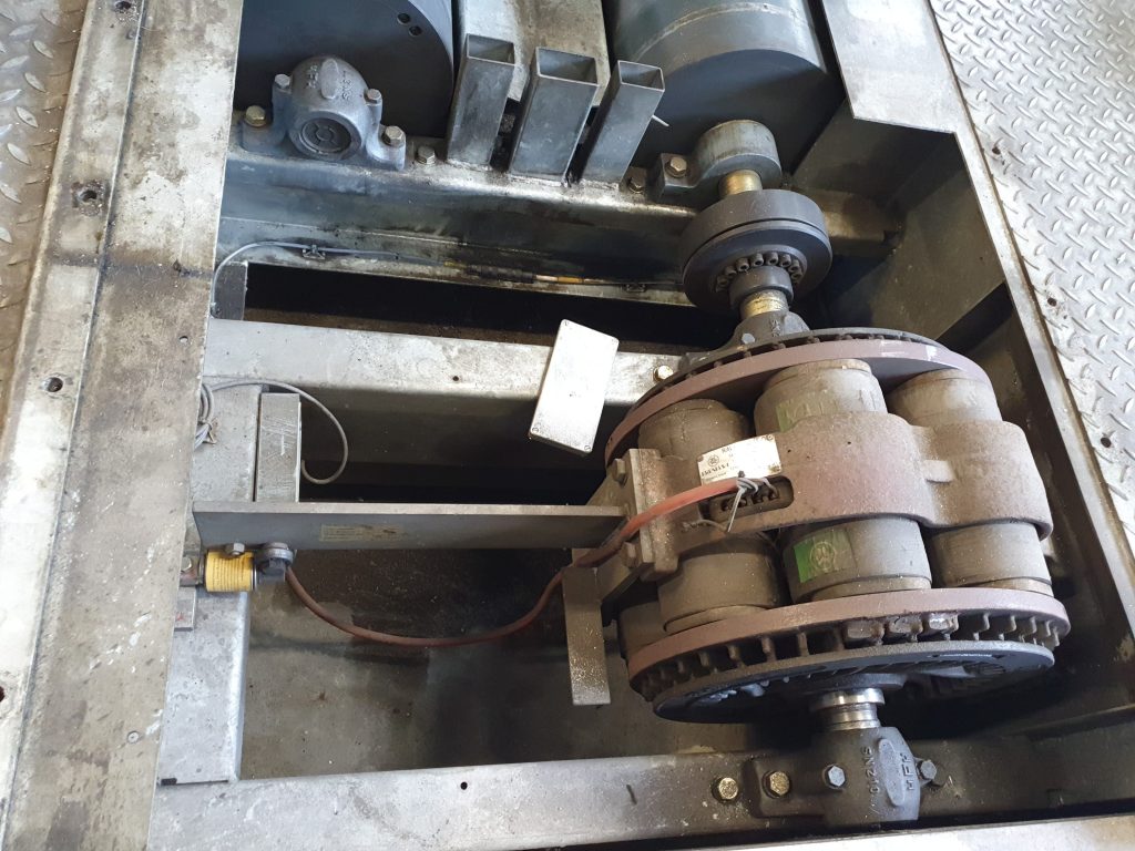
Eddy brake control
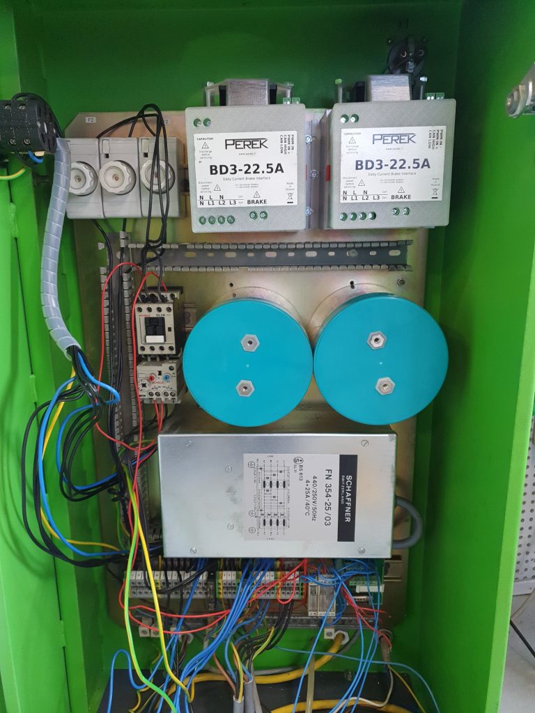
Bosch FLA is equipped with one Frenelsa F16-160 1600Nm eddy brake per axle. Newer models have a thermostatic switch that cuts off control signal when the break heats over 150°C. If the dyno was stored in poor conditions, the brake needs to be checked with an insulation tester to avoid short circuit and damage to the power supply.
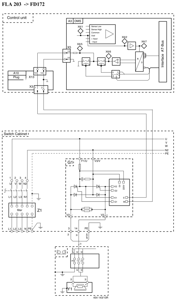
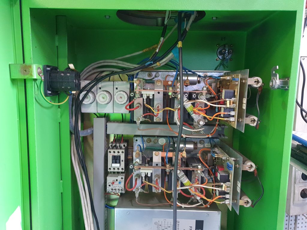
If the existing power supplies for eddy brake are operational, they can be reused. They are controlled with 0-10V analog signal. In case of reusing, the following connection pinout should be used:
Analog Output GND – Power Supply terminal ‘M’
Analog Output OUT – Power Supply terminal ‘E’ (through K2 relay if equipped)
If the stock power supply is damaged or if faster brake control is desired, the stock power supplies can be replaced with BD2 or BD3-22.5A-600uF. In that case, the eddy brake is connected directly to BD2 / BD3 and the thermostatic switch can be connected to Switch Input for monitoring and protection. Pay attention not to mix up eddy brake circuit with thermostatic switch. Connecting thermostatic switch to BD2 / BD3 output will damage the device. The line filter can be reused.
Pneumatic lifting step
For getting out of the rollers, Bosch FLA uses a pneumatic lifting step. Each step is controlled with a 12V pneumatic valve.
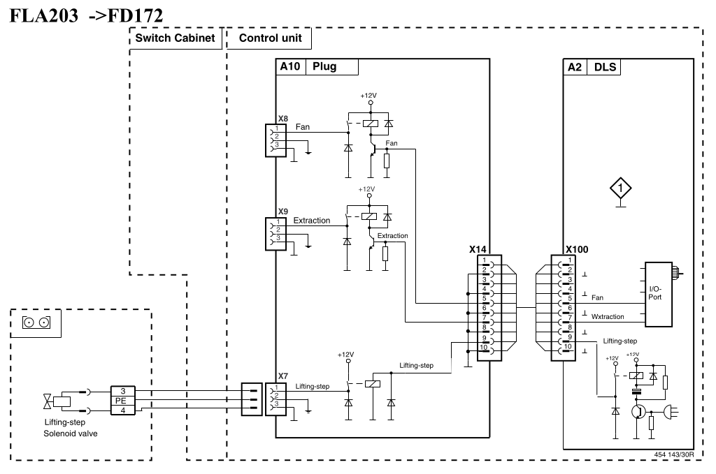
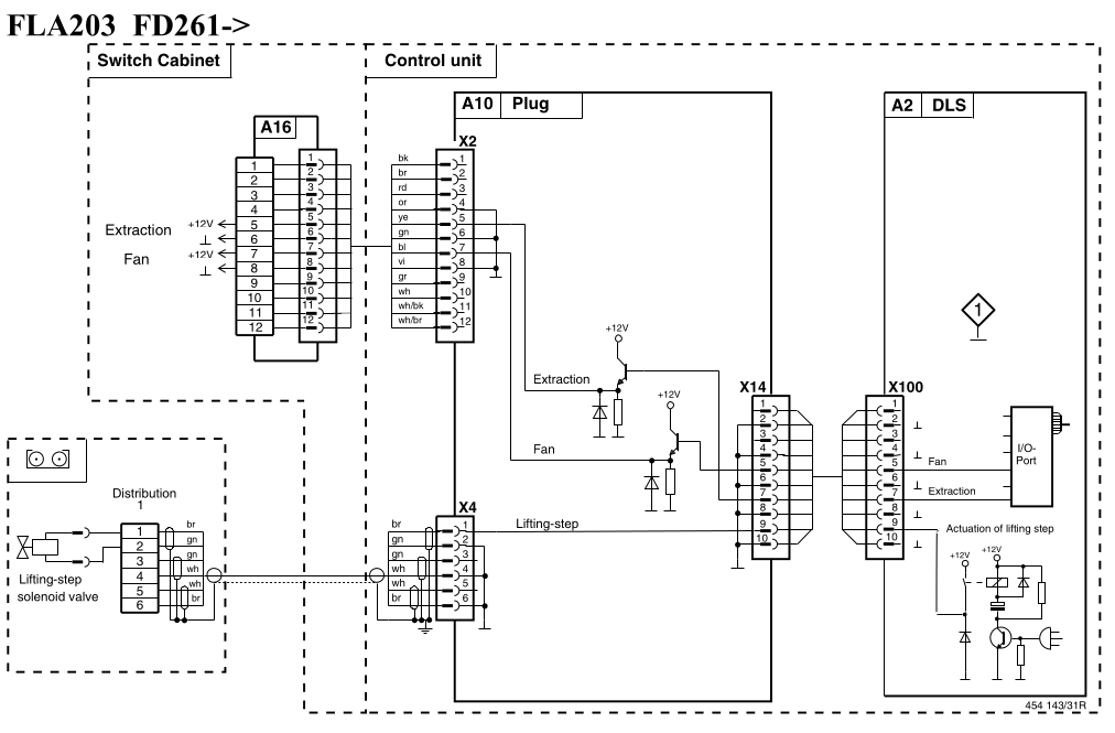
Each valve has two wires and uses 0.6A of current. Polarization is not important. One wire should be connected to a +12V source (it can be +12V from the controller), another wire to a low side output.
Suggested connection:
Low side out 1 – Lift 1
Low side out 2 – Lift 2
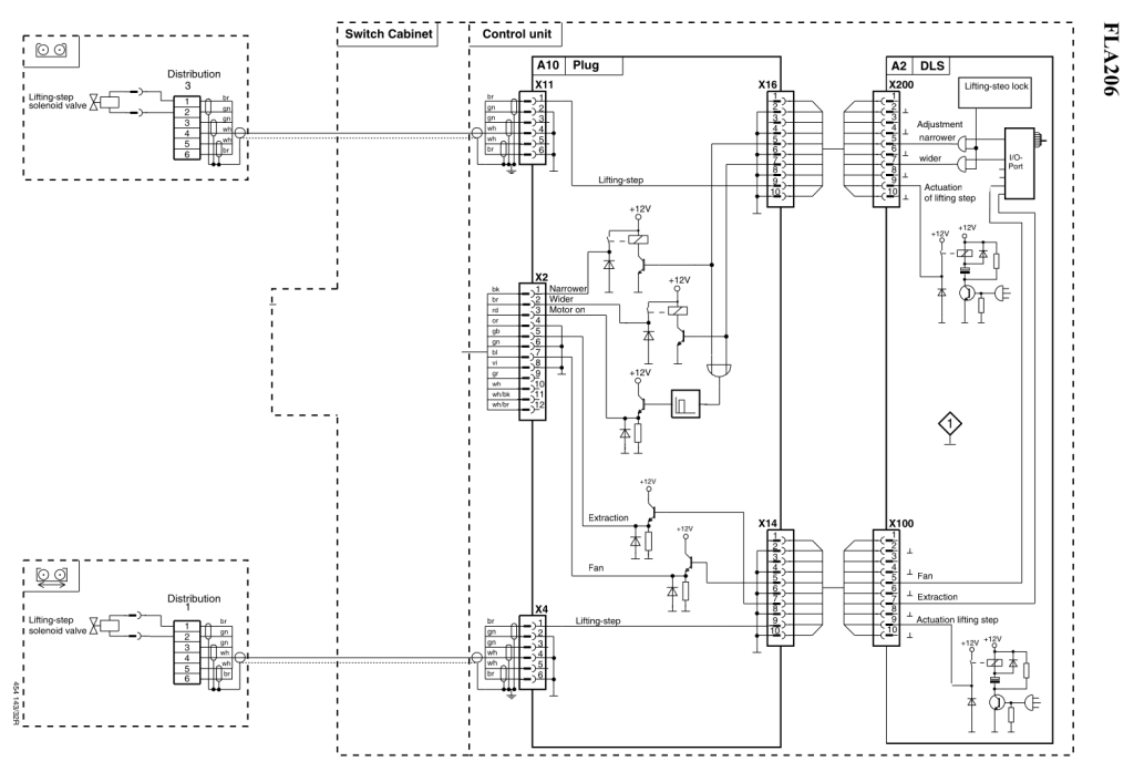
Wheelbase adjustment
Wheelbase adjustment in Bosch FLA 206 is executed with a hydraulic pump, two hydraulic valves and limit switches. To adjust the wheelbase, both the hydraulic pump and one of the valves must be activated at the same time.
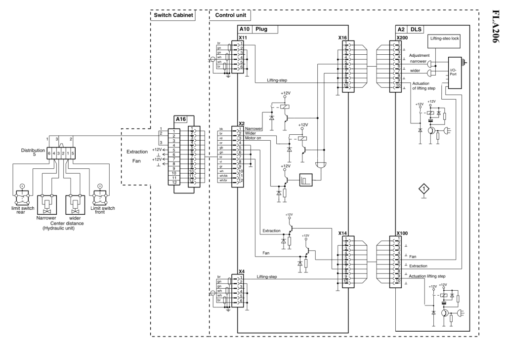
The +12V supply (wire 3) for the valves must be sourced from an external power supply, as each of the valves need 2.3A of current. Control signals (wires 1 and 2) should be connected to low side output OUT terminal in the dyno controller. The ground of external power supply must be connected with low side output GND.
Suggested connection:
Low side out 3 – wider valve
Low side out 4 – narrower valve
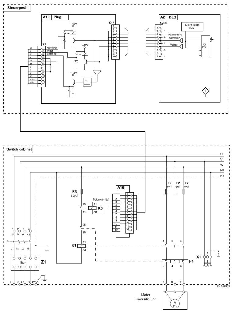
To control the hydraulic pump, the K3 relay may be replaced with a relay in the dyno controller. Wires from K3 terminals 13 and 14 should be connected to the relay terminals in the dyno controller. Polarization is not important.
Suggested connection:
Relay 1 – Hydraulic pump