Included in package:
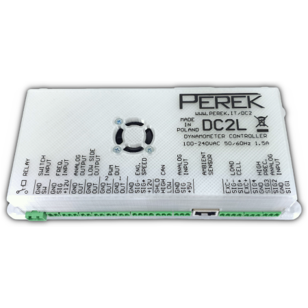
- DC2 controller
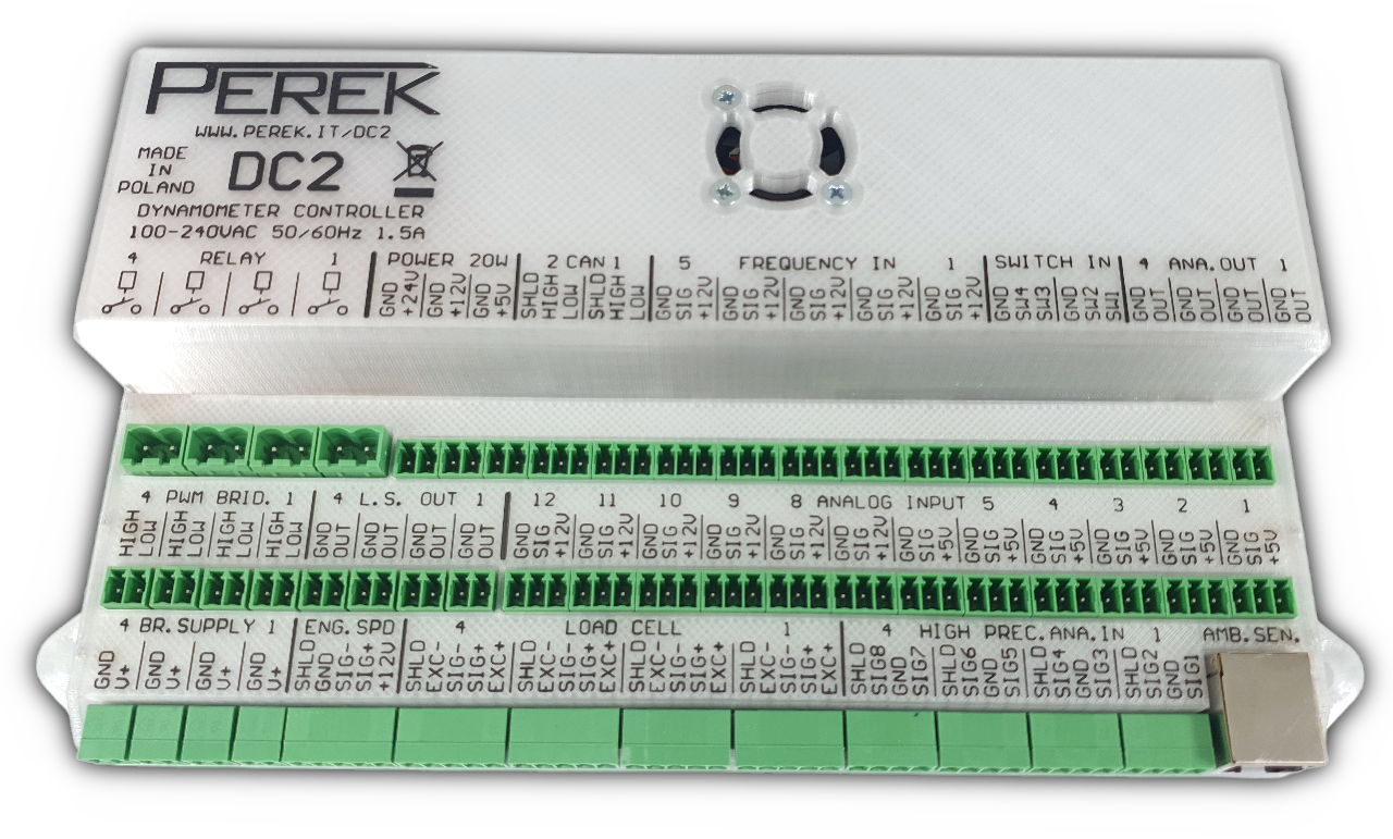
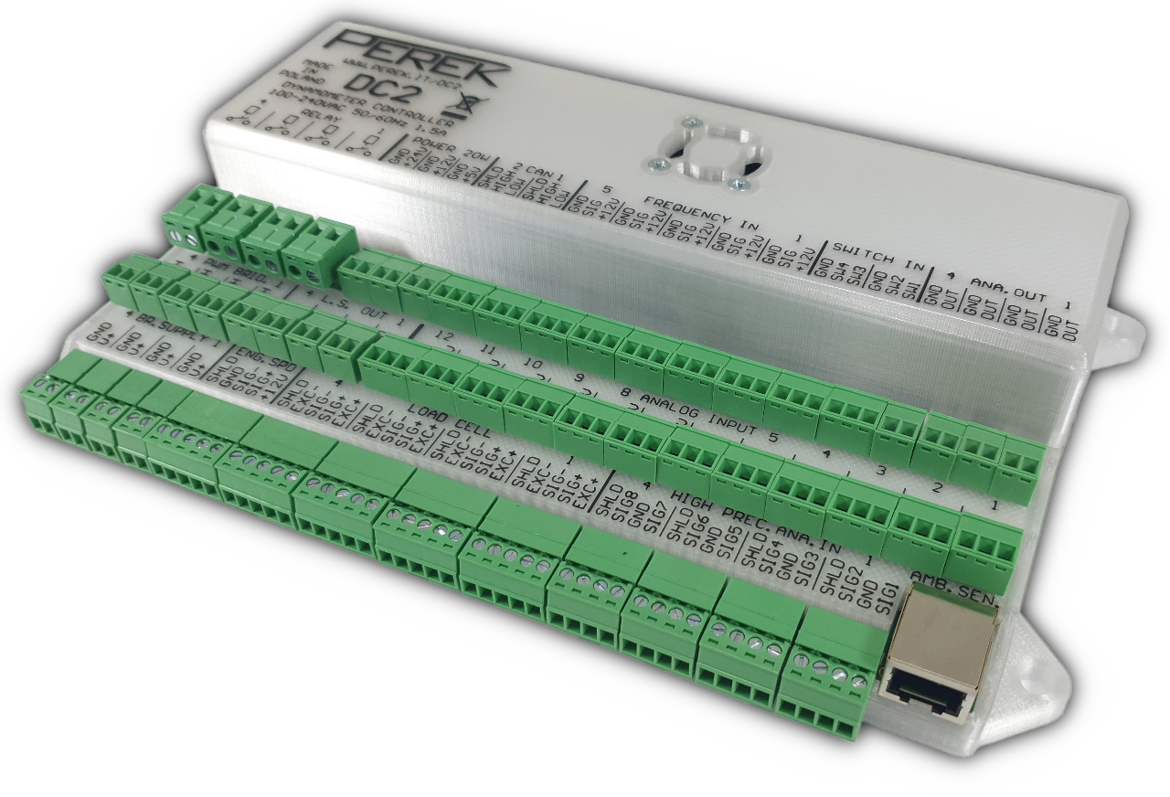
- full signal connector set
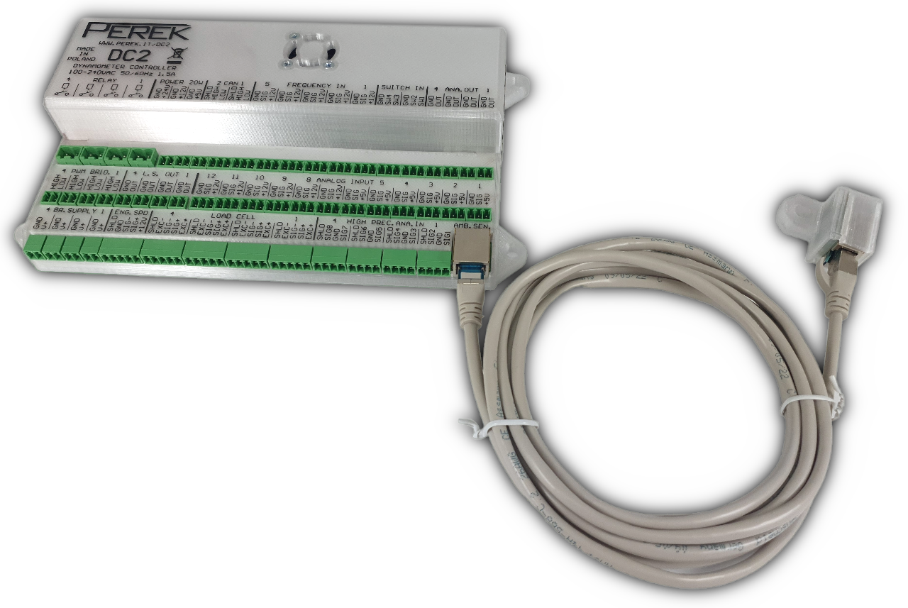
- weather station with cable
Specification
| Power supply | 100-240 VAC, 50-60Hz, 1.5A, IEC C14 socket |
| Ambient temperature | −20°C – 50°C |
| Ambient humidity | 0%-95% non condensing |
| Base computer | 4-core Cortex A76 2.4GHz 8GB RAM LPDDR4 Data memory 256GB 100MB/s |
| Microcontroller | 32-bit RISC 64MHz |
| Dimensions | 25cm x 14cm x 4.5cm |
| Mass | 0.61kg |
Inputs / outputs
- Wi-Fi IEEE 802.11b/g/n/ac (2,4/5 GHz)
- Bluetooth 5.0 (Low Energy (BLE))
- Gigabit Ethernet
- 2 x USB 2.0
- 2 x USB 3.0 (one occupied by data memory)
- 2 x micro HDMI
- Ambient condition sensor / weather station (temperature, pressure, humidity) included as a separate device
- 2 x CAN-BUS 2.0B
- Power outputs 24V, 12V, 5V(2A) with total capacity of 20W
- 4 analog outputs 0-10V
- 4 low side PWM outputs 3A 40V
- 4 high side PWM outputs 3A 28V
- 4 additional low side outputs 3A 40V
- 4 two-terminal relay outputs 250V 16A
- 4 hall sensor or encoder roller speed inputs up to 10Mhz
- 1 extra general purpose frequency input
- Engine speed input for hall, VR, inductive or capacitive clamp sensors up to 15kHz
- 4 dedicated load cell input with integrated amplifier
- 12 general purpose analog inputs 0-5V
- 8 thermocouple inputs
- 4 physical switch inputs
PC typical interfaces
The controller is equipped with typical interfaces, found in PC type computers, such as USB, Ethernet, micro HDMI. These allow to connect standard input / output devices such as mouse, keyboard, printer, display and internet connection. Wireless interfaces such as Wi-Fi and Bluetooth are also available.
Bluetooth enables wireless connection with vehicle OBD system, for readout of engine parameters, with use of optional interface.
Ambient sensor
The ambient sensor in the form of a separate device that connects to the main controller is included in the package. It is used to measure temperature, pressure and humidity which can be used to calculate corrected engine power according to common standards.
CAN-Bus interface
The controller is equipped with 2 independent CAN-Bus 2.0B interfaces, with transmission speed up to 1Mbps, compatible with ISO-11898-2 and ISO-11898-5.
Interfaces are equipped with software controlled 120Ohm terminating resistor.
CAN-Bus is routed with one twisted pair of wires and allows connecting many devices in parallel on one bus.
Example devices that can connected to the controller via CAN-Bus:
- Additional actuator drivers, H-bridges for servo motor control
- Additional input extenders – wideband oxygen sensor controller
- Automotive displays such as Ecumaster ADU
- Engine control units such as Ecumaster EMU Black, which can be used to read engine operation parameters or to control throttle opening
Power supply outputs
- 3 power supply outputs: 24V, 12V, 5V (2A), capable of total 20W power, enable to connect external modules with low-power requirements.
- Power outputs can be used to supply external relays and control them with low side outputs.
Analog outputs
- 4 analog outputs with 0-10V range are intended to control auxiliary dyno devices requiring analog signal.
- Can be used to control dyno absorber in retrofit applications.
- Output impedance: 1kOhm
- Resolution: 12bit
Low side and relay outputs
The controller is equipped with 8 low side outputs, capable of connecting terminal to ground (low side), and 4 outputs connecting to supply (high side).
- Maximum switched voltage low side: 40V
- Maximum switched voltage high side: 28V
- Maximum current: 3A continuous, 12A peak
- Maximum inductive load switching energy: 50mJ
- Short circuit and overload protected
4 of the low side and high side outputs have hardware PWM generation functionality and can generate PWM signal with frequency from 0.06Hz to 50kHz and resolution of 20bit. PWM outputs are capable of controlling:
- eddy current brakes (with use of external BD1 brake power supply)
- solenoid valves
- servo motors compatible with RC pulse signal
- power modulation of devices such as cooling fans etc.
Low side and high side outputs can be joined into half or full bridge to enable bidirectional control of DC motors.
High side outputs have current measurement functionality.
Remaining 4 low side outputs and 4 relay outputs are controlled with programmable logic and allow to power auxiliary devices according to operating conditions or user input. Example use cases are:
- automatic fan turn on above preset engine speed
- starter motor control from dyno keyboard
Relay output capacity is 250V 16A.
Frequency inputs
The controller is equipped with 6 frequency inputs.
5 inputs support hall sensors, encoders and any other sensor generating a frequency signal. 4 of them are intended for measuring chassis dyno roller rotational speed or for engine dyno to measure dyno main shaft rotational speed. In „pulse capture” mode, acceptable input frequency is 15mHz to 15kHz. In „pulse count” mode, frequency up to 10Mhz is accepted.
- Maximum input signal voltage: 15V
- Signal threshold voltage: 2.5V
- Hysteresis: 0.6 – 1.2V
The last input allows reading signal from Hall, VR, inductive or capacitive clamp sensors. It can be used to read engine speed in cases where the speed is not in constant relation with dyno roller or shaft speed.
- Input voltage up to 50VAC sine, 250V peak
- Differential input
- Adaptive signal arming threshold
Load cell input
The controller has 4 dedicated, differential high precision inputs with built-in programmable amplifier for direct connection of load cells.
- Amplification range: 1-128
- Differential voltage range: 4V
- Voltage on inputs for measurement: 0.5V – 4.5V
- Allowable voltage on inputs: 0V – 5V
- Resolution: 24bit
- Logging frequency: 500Hz
- Sampling frequency: 256kHz
Analog inputs
The device has 12 analog inputs with 0-5V range. The inputs can be used to connect any additional sensors.
- Maximum input voltage: 30V
- Resolution: 14bit
- Logging frequency: 500Hz
- Sampling frequency: 25kHz
High-precision analog inputs
The device has 4 differential pairs or high precision analog inputs. These inputs can be used for direct thermocouple connection or for connection of any sensor giving signal in 0-5V range. Every pair allows measuring signal in differential or single-ended mode. The single-ended mode allow connection of 8 sensors total.
- Resolution: 16bit
- Logging frequency: 10Hz
- Sampling frequency: 250kHz
- Voltage ranges: 0-256mV to 0-5V
Switch inputs
The device has 4 inputs for switch connection. A switch can be used to activate software functions or controller outputs.