CS2 speed sensor is an inductive sensor used to measure rotational engine rotational speed from ignition coil power or high voltage wires. The sensor is used when a vehicle doesn’t have an engine tachometer or when the gearbox ratio is not constant (hydrokinetic transmission). The sensor is designed to work with DC series dyno controller.
CS2 is an upgraded version of the older CS1 sensor. It has improved compatibility with high voltage ignition cable signal and manual sensitivity adjustment for better noise rejection.
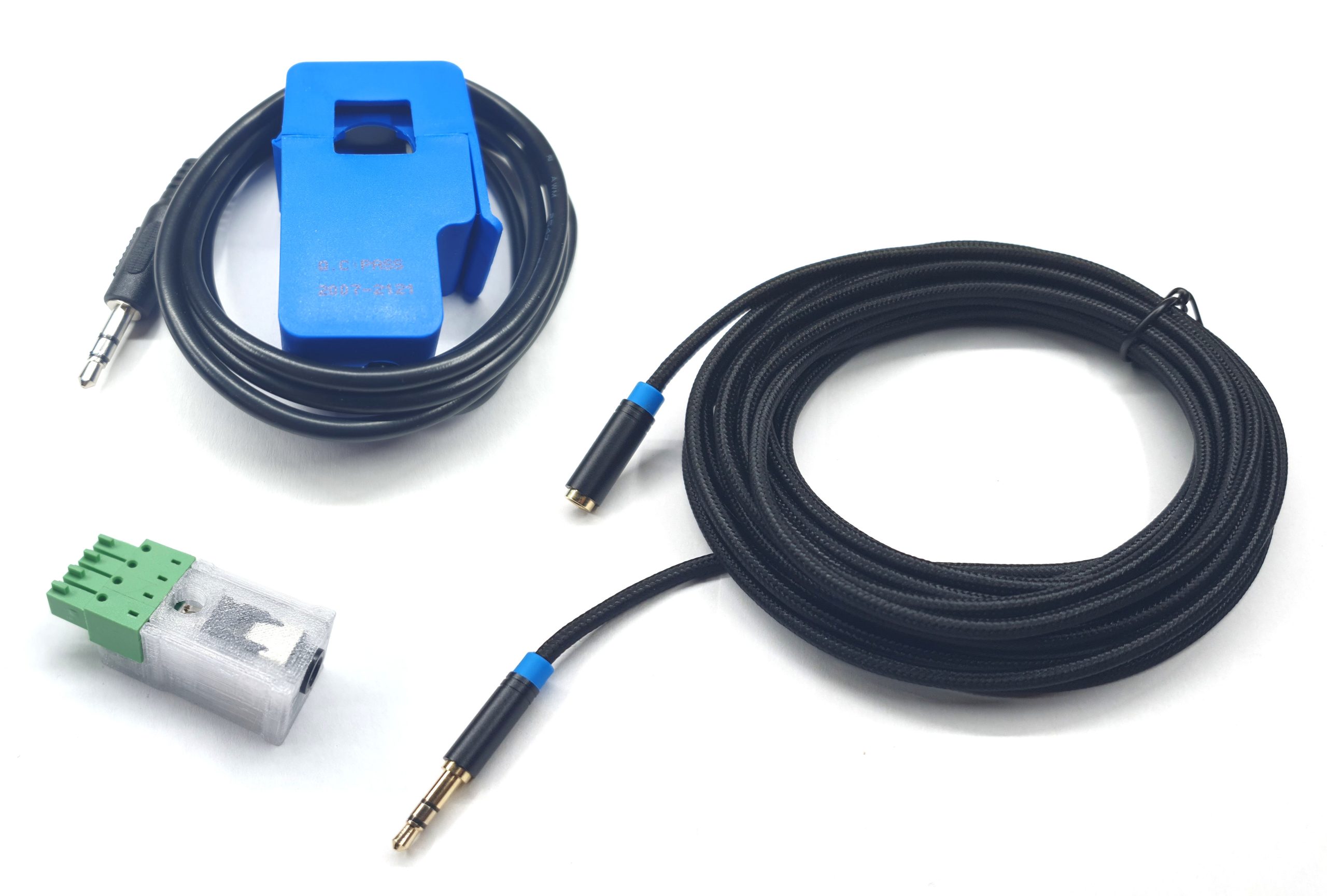
Kit components
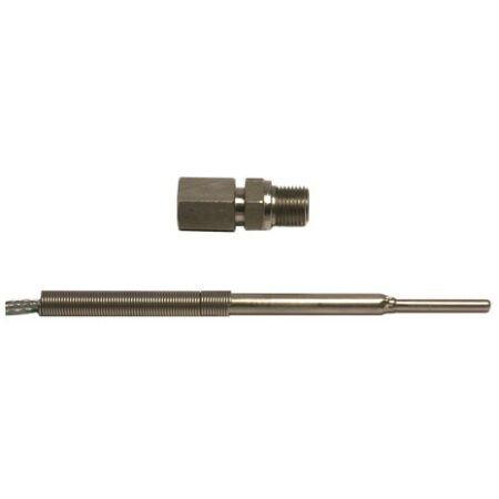
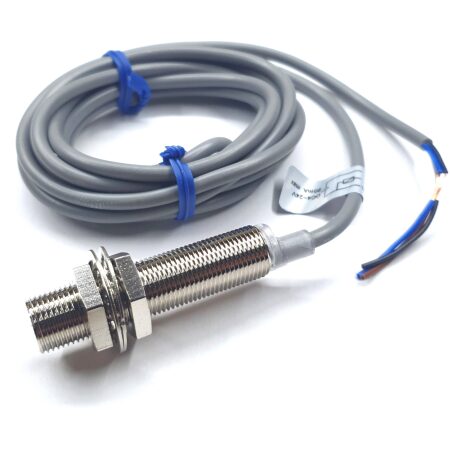
- Inductive sensor
- 5m extension cable
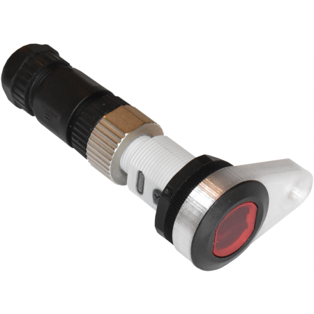
- Adapter with sensitivity adjustment
The sensor should be connected to the Engine Speed input in the controller.
The inductive sensor is best at detecting signals that have significant current. Example sources for signals are wires for:
- injectors
- ignition coils power
- high voltage spark plug cable
Due to ignition spark characteristic, current signal on high voltage cable can be unstable, what can result in noisy speed signal. Best practice to use in this case is to use the sensor to read Engine / Roller speed ratio and then make measurements in constant ratio mode: Eng. speed source: calculated.
Usage instructions
- Clamp the probe on the cable
- With PH1 or flathead 2 – 2.5 screwdriver, adjust the sensitivity in the adapter until some signal appears. Clockwise – more sensitive. Counterclockwise – less sensitive.
- Fine adjust while looking at the speed signal and changing the engine speed:
- Spikes on the signal dropping to half of real frequency – increase sensitivity or if used decrease “Next edge rejection time”.
- Spikes on the signal going to higher-than-real frequencies – decrease sensitivity or reverse the clamp probe on the cable and/or increase “Next edge rejection time”.
- Adjust “Signals per rotation” and/or “Speed multiplier” to match then number of signals generated by your source per engine rotation.
The relevant setting can be found in SETTINGS / Frequency Input / Engine speed.
Next edge rejection time rejects signals for a configured time. It can be useful to ignore echoes of the main signal for some time.
Best general purpose settings is 2ms
If for example your signal goes up to 200Hz then the useful signal period is 1/200Hz = 5ms. The rejection time must be lower than this value.
The current version of adapter has an enclosure piece for positioning the plug in the 5 pin socket. In case of a controller with 4 pin socket, the positioning element should be cut out.
![]()